Message transmission method, device and system
A message transmission and message technology, applied in the field of communication, can solve the problems of low efficiency of the TDM business system, and achieve the effect of solving low efficiency and quickly switching routes
- Summary
- Abstract
- Description
- Claims
- Application Information
AI Technical Summary
Problems solved by technology
Method used
Image

Examples
Embodiment 1
[0028] The invention relates to the field of communication, in particular to equipment and systems requiring SDH and PDH technology for service transmission using simulated messages. In particular, the landing equipment at the core layer needs to protect services across equipment. The service model of the present invention can achieve service protection across devices.
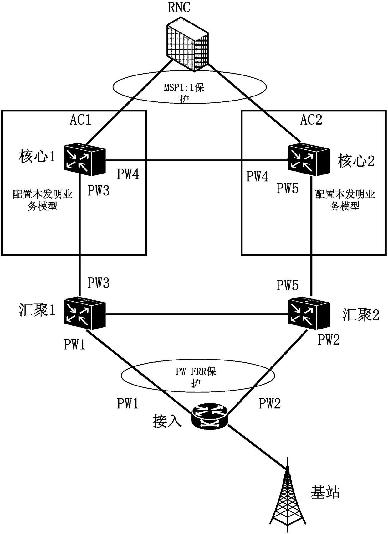
[0029] The embodiment of this application can run on image 3 On the network architecture shown, such as image 3 As shown, the network architecture includes: a wireless manager RNC, two core devices, two aggregation devices, and one access device.
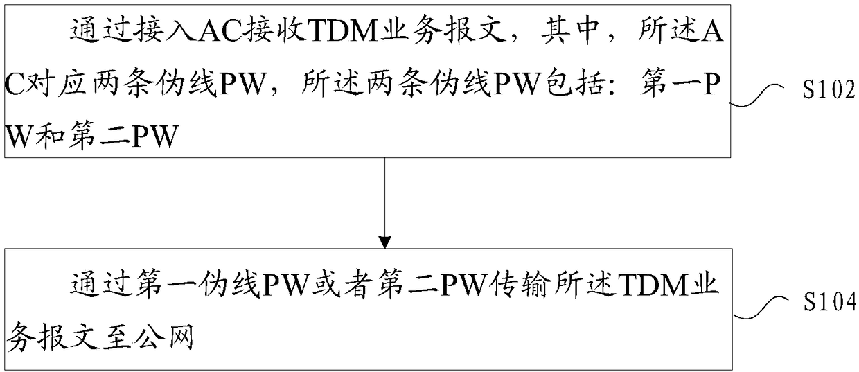
[0030] In this embodiment, a message transmission method running on the above-mentioned network architecture is provided, figure 1 is a flowchart of a message transmission method according to an embodiment of the present invention, such as figure 1 As shown, the process includes the following steps:
[0031] Step S102, receiving the TDM service message by acc...
Embodiment 2
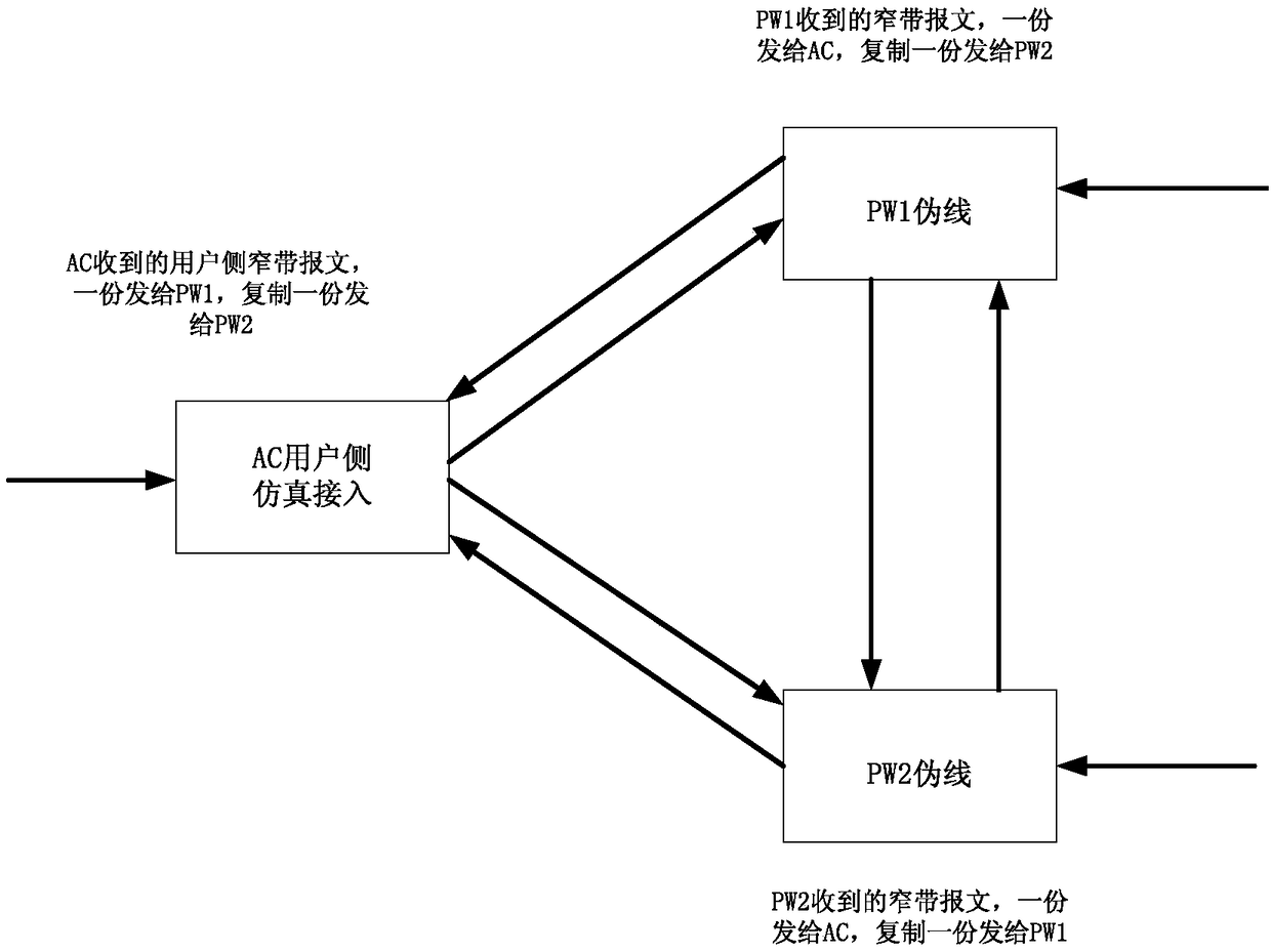
[0039] According to another embodiment of the present invention, a message transmission device applied to the construction of the message transmission method of the present invention is also provided, figure 2 is a schematic structural diagram of a message transmission device according to an embodiment of the present invention, such as figure 2 As shown, the message transmission device includes an AC and two pseudowires PW, and the two pseudowires are set corresponding to the AC, that is, the AC is a receiving or sending port of the device, and the two pseudowires are another sending port of the device. Or the receiving port, the AC is used to receive the TDM service message; the first PW is used to transmit the TDM service message received by the AC to the public network; or the second PW is used to transmit the TDM service message The TDM service packets received by the AC are sent to the public network.
[0040] Optionally, the second PW is further configured to transmit...
Embodiment 3
[0042] According to another embodiment of the present invention, a message transmission system is provided, image 3 is an architecture diagram of a message transmission system according to an embodiment of the present invention, such as image 3 As shown, in the first core device of the system (equivalent to image 3 Core 1 shown) and a second core device (equivalent to image 3 The structure of the above-mentioned message transmission device is applied to the shown core 2), that is, the first core device is connected to the first aggregation device through the third PW, and connected to the second core device through the fourth PW, and the first core device is connected to the first convergence device through the fourth PW. A core device is connected to the wireless controller RNC through the first access AC; the second core device is connected to the second convergence device through the fifth PW, and the second core device is connected through the fourth PW It is connect...
PUM
 Abstract
Description
Claims
Application Information
 - R&D Engineer
- R&D Manager
- IP Professional
- Industry Leading Data Capabilities
- Powerful AI technology
- Patent DNA Extraction
Browse by: Latest US Patents, China's latest patents, Technical Efficacy Thesaurus, Application Domain, Technology Topic.
© 2024 PatSnap. All rights reserved.Legal|Privacy policy|Modern Slavery Act Transparency Statement|Sitemap