Positioning parking system
A technology for parking systems and vehicles, applied in the field of positioning parking systems, can solve the problems of increasing the construction and maintenance costs of public bicycle systems, reducing the bicycle parking density at car rental sites, and the large proportion of car lock piles, etc., so as to facilitate citizens to travel, Save the time and process of returning the car, and reduce the effect of operating costs
- Summary
- Abstract
- Description
- Claims
- Application Information
AI Technical Summary
Benefits of technology
Problems solved by technology
Method used
Image

Examples
Embodiment 1
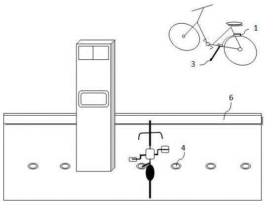
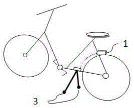
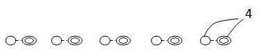
[0030] Such as figure 2 As shown, the parking sensing unit 2 adopted in this embodiment is a magnetic sensing component, and the magnetic sensing component is a well-known technology, so it will not be repeated here. The vehicle-mounted information manager 1 and the sensor 3 are magnetic components installed on the bicycle, such as a reed switch 31. In order to meet the trigger distance, the reed switch 31 can be arranged on the bicycle support feet or the lower frame near the ground, using wired Or be electrically connected with the vehicle information manager 1 in a wireless manner. On the car rental site, a ground sensor 4, such as a magnetic steel 41, is provided, and a prominent mark is made at this position. When the reed switch 31 approaches the magnetic steel 41, it is triggered under the action of the magnetic field. The magnetic steel 41 in this embodiment is a passive sensor, which can be easily installed on the ground. It only needs to drill a hole on the ground at
Embodiment 2
[0033] The parking sensing unit 2 used in this embodiment is a chip 42 and a card reader 32. The chip 42 can adopt technologies such as IC chips and RFID radio frequency identification chips, which are known technologies and will not be described here. In this embodiment, the bicycle is provided with an electrically connected information manager 1 and a card reader 32. The card reader 32 can be arranged on the legs or near the ground of the vehicle, and an induction chip 42, such as an RFID chip, is arranged on the ground. , The RFID chip internally stores information such as parking space codes. When the user returns the car, the card reader 32 reads the RFID chip information, and transmits the sensing information 5 to the vehicle information manager 1, and the information manager 1 judges the parking after receiving it. In this embodiment, the RFID chip installed on the ground is passive, and the card reader 32 reads the parking space code and feeds it back to the information m
Embodiment 3
[0035] In this embodiment, a contact chip is used as the sensor 4 to be arranged on the ground, and the sensor 3 on the vehicle is two positive and negative contact wires, and the wires are connected to the information manager 1 . When actually parking, the positive and negative wires on the vehicle are in contact with the positive and negative electrodes of the sensor 4 chip, and the carrier circuit is used to transmit the chip information for parking space management and realize parking space positioning.
PUM
 Abstract
Description
Claims
Application Information
 - R&D Engineer
- R&D Manager
- IP Professional
- Industry Leading Data Capabilities
- Powerful AI technology
- Patent DNA Extraction
Browse by: Latest US Patents, China's latest patents, Technical Efficacy Thesaurus, Application Domain, Technology Topic.
© 2024 PatSnap. All rights reserved.Legal|Privacy policy|Modern Slavery Act Transparency Statement|Sitemap