LED drive circuit based on single chip microcomputer and replacement circuit method

A technology of LED driving and circuit replacement, which is applied in the direction of electric lamp circuit layout, electric light source, lighting device, etc., can solve the problems of poor reliability, high energy consumption, other components cannot work, etc., to reduce energy consumption and line current. Effect

Inactive Publication Date: 2016-02-03
ZHEJIANG UNIV
View PDF5 Cites 0 Cited by
  • Summary
  • Abstract
  • Description
  • Claims
  • Application Information

AI Technical Summary

Benefits of technology

This patented technology helps solve problems with existing serial-driven lighting systems caused by single LED failure due to overcurrent flow during operation. It also reduces power usage without affecting their overall performance.

Problems solved by technology

This patented technical problem addressed in the patents relates to improving the efficiency at which LED lights work over time without consuming excessive amounts of electricity or causing damage from increased temperature caused by the use of serially connected LED devices.

Method used


Image

  • LED drive circuit based on single chip microcomputer and replacement circuit method

Examples


Embodiment Construction

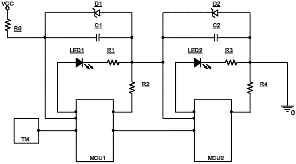
[0015] figure 1 What is shown is the LED driving circuit based on the single chip microcomputer and the alternative circuit method, which is a circuit structure for controlling the situation of two LEDs. It includes a power supply module, a transmitting module and two sequentially connected LED driving units; the LED driving unit includes: an MCU, a voltage stabilizing module, a replacement circuit module and an LED branch circuit.

[0016] The power module includes a VCC power supply and a power protection resistor R0;

[0017] The transmitting module is a data generation unit TM, which sends control information to the two LEDs to the MCU1 of the first LED drive unit; generally, a computer control platform can be used to send data to the MCU1, and the data includes information for controlling each LED;

[0018] The voltage stabilizing module in the LED drive unit is composed of a capacitor C and a voltage stabilizing tube D connected in parallel, the replacement circuit module


PUM


Abstract

The invention discloses an LED drive circuit based on a single chip microcomputer and a replacement circuit method. The LED drive circuit comprises a power supply module, a transmitter module and a plurality of LED drive units, wherein the LED drive units are sequentially connected with one another; each LED drive unit comprises an MUC, a voltage stabilization module, a replacement circuit module and an LED branch; the MCUs of the LED drive units are sequentially connected with one another; and each MCU obtains information for controlling a corresponding LED after receiving data output by the previous MCU, and outputs the residual data to the next MCU. According to the LED drive circuit, the problem that the whole circuit cannot normally work due to the fact that one LED in a traditional tandem drive LED circuit is damaged is solved, so that the LEDs in the whole circuit can be lightened or extinguished according to the actual requirements. In addition, the problem of over-high line current in the traditional parallel drive LED circuit is solved by the drive circuit disclosed by the invention; the line current can be effectively reduced; and energy consumption is reduced.

Description


Claims


Application Information

Patent Timeline
Owner ZHEJIANG UNIV
Why Eureka
Try Eureka