Sand casting die for casting of lower connecting plate

A mold and connecting plate technology, applied in the direction of manufacturing tools, casting molding equipment, casting molds, etc., can solve the problems of the number of cavity plates, reduce production efficiency, cumbersome procedures, etc., achieve low production cost, reduce production time and Effects of cost and process reduction

Pending Publication Date: 2016-03-02
张越
View PDF11 Cites 0 Cited by
  • Summary
  • Abstract
  • Description
  • Claims
  • Application Information

AI Technical Summary

Benefits of technology

This new method uses cast-on molds instead of traditional methods for making metal parts like steel pipes or tubulars that require expensive machining processes such as cutting off material from them before they are used again. By reducing costs while producing high quality products by utilizing this technology, it becomes more economically viable than current options.

Problems solved by technology

This patented technical problem addressed in this patents relating to improving safety and ease for drivers during turning maneuvers on road vehicles has been caused due to poor connection between the rear bumper's suspension system and the vehicle body itself. Prior designs had limitations such as reduced space available within certain areas or increased weight compared to other design options.

Method used


Image

  • Sand casting die for casting of lower connecting plate
  • Sand casting die for casting of lower connecting plate
  • Sand casting die for casting of lower connecting plate

Examples


Embodiment Construction

[0020] The present invention will be further described below in conjunction with accompanying drawing with specific embodiment:

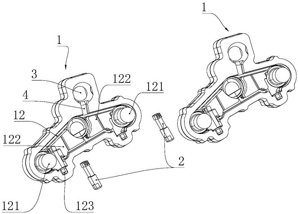
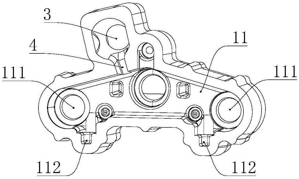
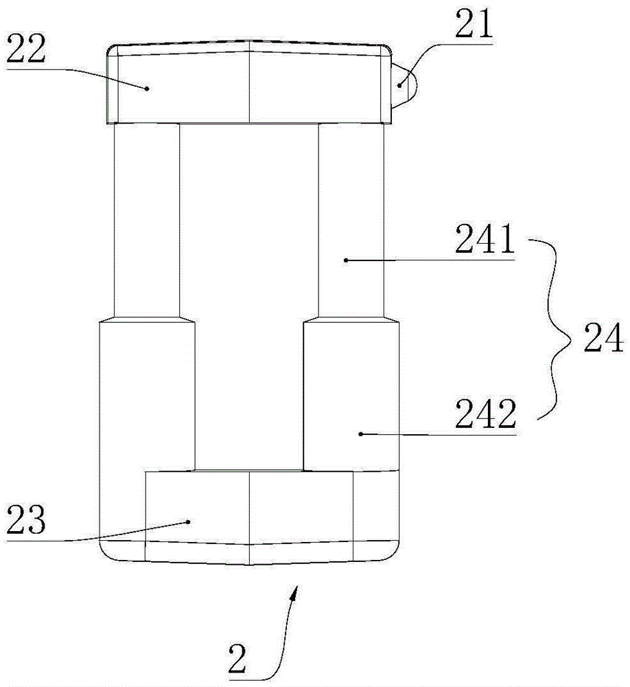
[0021] see figure 1 , figure 2 , image 3 As shown, a sand casting mold for casting the lower connecting plate includes at least two cavity plates 1 superimposed on each other, and N cores 2, where N is an even number; the cavity plates 1 are arranged in a horizontal arrangement, The use of sand casting molds makes the production cost lower, and the cycle of the casting mold is shorter. Through the horizontal arrangement of the cavity plates 1, the connecting plates can increase the number of cavity plates 1 arranged in one molding to increase the number of moldings at one time. Reduce production time and cost; The left end face of described die cavity plate 1 is provided with concave die cavity 11, and the right end face of described die cavity plate 1 is provided with punch die cavity 12, and described punch die cavity 12 and adjacent The die cav


PUM


Abstract

The invention belongs to the technical field of machine manufacturing, in particular to a sand casting die for casting of a lower connecting plate. The sand casting die is high in production efficiency and simple in process, and comprises at least two mutually overlaid die cavity plates and N cores, wherein N is an even number; the die cavity plates are transversely arranged; a female die cavity is arranged on the left end surface of each die cavity plate, and a male die cavity is arranged on the right end surface of the die cavity plate; the male die cavity is matched with the female die cavity of the adjacent die cavity plate; two symmetrically arranged cylinders and two symmetrically arranged lug bosses are arranged in each male die cavity; two grooves I opening outwards and communicated with the male die cavity are formed in the side wall of the male die cavity; two grooves II opening outwards and communicated with the female die cavity are formed in the side wall of the female die cavity; the grooves I are respectively formed between the cylinders and the lug bosses; the grooves I are matched with the grooves II of the adjacent die cavity plate; one ends of the cores are arranged in the grooves I, and bulges are arranged at the other end of the cores; the end surfaces of the bulges are higher than the side surfaces of the lug bosses, and are propped against the side wall of the female die cavity of the adjacent die cavity plate.

Description


Claims


Application Information

Patent Timeline
Owner 张越
Why Eureka
Try Eureka