Foam separating and purifying device

A foam separation and defoamer technology, which is applied in the chemical industry, can solve the problems of low efficiency of continuous process devices, reduced overall process economic benefits, and no continuous process devices, etc., and achieves improved separation and purification efficiency, high purity and purification efficiency. , the effect of saving space

Inactive Publication Date: 2016-03-09
TIANJIN ANHAO PHARMATECH CO LTD
View PDF0 Cites 1 Cited by
  • Summary
  • Abstract
  • Description
  • Claims
  • Application Information

AI Technical Summary

Benefits of technology

This new design for separating and cleaning foams includes an improved apparatus called a separator or clarifier. It uses heat from both radiation and gravity to separate liquids before they reach another chamber where filters work together to remove impurities like dirt particles. By doing this, these devices improve their performance over existing methods while still being costly due to its large size. Additionally, there's no extra equipment needed outside the main machine itself, making them more compact than traditional systems. Overall, this technology helps produce higher-quality products by enhancing the effectiveness and economy of current processes used for producing foamed plastic parts.

Problems solved by technology

This patented technical problem addressed by this patents relates to improving the efficient use of chemical separations for various applications like protein isolating from liquid mixtures containing different types of molecules at high concentrities with minimal energy consumption compared to traditional methods that require expensive equipment.

Method used


Image

  • Foam separating and purifying device

Examples


Embodiment Construction

[0023] It should be noted that, in the case of no conflict, the embodiments of the present invention and the features in the embodiments can be combined with each other.

[0024] In describing the present invention, it should be understood that the terms "center", "longitudinal", "transverse", "upper", "lower", "front", "rear", "left", "right", The orientations or positional relationships indicated by "vertical", "horizontal", "top", "bottom", "inner", "outer", etc. are based on the orientation or positional relationships shown in the drawings, and are only for the convenience of describing the present invention Creation and simplification of description, rather than indicating or implying that the device or element referred to must have a specific orientation, be constructed and operate in a specific orientation, and therefore should not be construed as limiting the invention. In addition, the terms "first", "second", etc. are used for descriptive purposes only, and should not b


PUM


Abstract

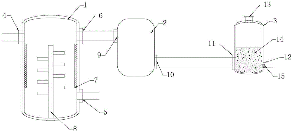
The invention provides a foam separating and purifying device which comprises a rectifying tower, a filter and a foam breaker. The rectifying tower is connected with the filter, and the filter is connected with the foam breaker. A rectifying tower liquid inlet and a rectifying tower exhaust port are formed in the upper end of the rectifying tower and oppositely formed. A rectifying tower liquid outlet is formed in the lower end of the rectifying tower, a heater is arranged on the inner wall of the rectifying tower, and a stirrer is arranged in the rectifying tower. A foam breaker inlet and a foam breaker outlet are formed in the lower end of the foam breaker, the foam breaker inlet is connected with a filter outlet through a pipeline, the foam breaker inlet is opposite to the foam breaker outlet, a filter film is arranged on the foam breaker outlet, and filler is arranged in the foam breaker. The foam separating and purifying device is provided with the rectifying tower, the filter and the foam breaker at the same time, materials are firstly separated, then filtered and finally purified, and the high purity and purifying efficiency of a separated and purified product are ensured.

Description


Claims


Application Information

Patent Timeline
Owner TIANJIN ANHAO PHARMATECH CO LTD
Why Eureka
Try Eureka