Crane capable of being integrally lowered

A technology of overall height and crane, applied in the direction of trolley cranes, cranes, load trolleys, etc., can solve the problems of inconvenient use of enterprises and large loss of lifting height of double-girder cranes, and achieve a light frame, reduce the weight of the trolley, reduce the The effect of cart height

Inactive Publication Date: 2016-05-25
SUZHOU BEITELUO INTELLIGENT TECH CO LTD
View PDF5 Cites 0 Cited by
  • Summary
  • Abstract
  • Description
  • Claims
  • Application Information

AI Technical Summary

Benefits of technology

This new type of lift used for construction has two beams instead of one beam. It's easy because it doesn’t have any moving parts like an old system or its own hoist mechanisms. Additionally, this design allows for easier movement without adding extra weights on top while still being able to support heavy loads over long distances.

Problems solved by technology

This patented technical solution involves improving universal bridges that can carry more weight without sacrificing its strength or stability. However, current solutions have limitations such as requiring high overhead for maintenance staffs who install them on top of the industrial buildings themselves. Additionally, there may be issues with elevated levels caused by adding an extra part like a runway system at one location where it'll affect safety regulations.

Method used


Image

  • Crane capable of being integrally lowered
  • Crane capable of being integrally lowered

Examples


Embodiment Construction

[0012] The present invention will be further described below in conjunction with accompanying drawing:

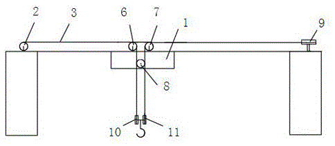
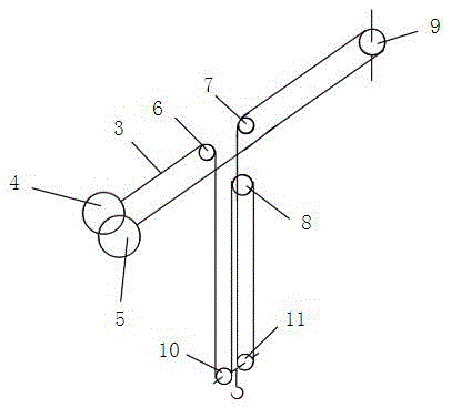
[0013] A crane capable of reducing the overall height, comprising a trolley (1), a reel (2), the reel (2) is arranged on the left beam end, the reel (2) is connected to a motor, and a steel wire (3 ), characterized in that the steel wire (3) is wound with a first planar helical coil (4) and a second planar helical coil (5) on the reel (2), and the first planar helical coil (4 ) is in the same winding direction as the second planar helical coil (5), and the trolley (1) is fixed with a first wheel (6) and a second wheel (7) on one side of the main beam, and the trolley (1) ) A fixed pulley (8) is fixed on one side of the other main beam, and a horizontal fixed pulley (9) is fixed on the right beam end, and the steel wire (3) is wound into the first plane spiral coil (4) and then wound Pass the first wheel (6), then bypass the first movable pulley (10), then bypass the fixed pul


PUM


Abstract

The invention provides a double-beam bridge crane which is unlikely to be limited by the height of a plant. The double-beam bridge crane comprises a trolley, a coiling block and a steel wire, wherein the coiling block is arranged on a left beam end and is connected with a motor; the steel wire is wound with a first plane spiral coil and a second spiral coil on the coiling block on the left beam end, and the winding directions of the first plane spiral coil and the second spiral coil are the same; a first trolley wheel and a second trolley wheel are fixed on one side, on a main beam, of the trolley, and a fixed pulley is fixed on one side, on another main beam, of the trolley; a horizontal fixed pulley is fixed on a right beam end; and after forming the first plane spiral coil, the steel wire sequentially bypasses the first trolley wheel, a first movable pulley, the fixed pulley, a second movable pulley, the second trolley pulley and the horizontal fixed pulley and finally winds the coiling block to form the second plane spiral coil. According to the crane, the original operation mechanisms and hoisting mechanism are not used, so that the trolley is lightened and lowered, then the complete machine is lowered, and thus a trolley frame is relatively light and convenient.

Description


Claims


Application Information

Patent Timeline
Owner SUZHOU BEITELUO INTELLIGENT TECH CO LTD
Why Eureka
Try Eureka