Novel pipeline blockage detection device

A technology for clogging detection and pipelines, applied in pipeline systems, mechanical equipment, gas/liquid distribution and storage, etc., can solve the problems of low detection efficiency and labor consumption, and achieve the effect of satisfying detection requirements and effective detection

Inactive Publication Date: 2016-06-01
CHENGDU XUNDE SCI & TECH
View PDF7 Cites 4 Cited by
  • Summary
  • Abstract
  • Description
  • Claims
  • Application Information

AI Technical Summary

Problems solved by technology

[0003] However, with the rapid development of underground pipelines, more and more management problems have been brought about, and urban waterlogging, water and power cuts and other problems caused by the blockage of underground pipelines have also brought great harm to urban residents. Influence
At present, the maintenance of underground pipelin

Method used


Image

  • Novel pipeline blockage detection device

Examples


Embodiment Construction

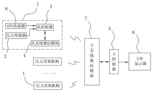
[0015] Such as figure 1 As shown, a novel pipeline blockage detection device includes a main controller 5, and also includes a plurality of pressure acquisition mechanisms 1 uniformly arranged along the length direction of the pipeline. The pressure acquisition mechanism 1 sequentially includes a pressure sensor 2, a slave controller 3 and from the wireless communication module 4, the pressure sensor 2 is located on the inner wall of the pipeline, and the output end of the pressure sensor 2 is connected to the input end of the slave controller 3, and the communication end of the slave controller 3 is connected to the input of the wireless communication module 4 The output end of the main controller 5 is also connected with an LCD display 6, and the communication end of the main controller 5 is also connected with a main wireless communication module 7, and the main wireless communication module 7 and the slave wireless communication of the pressure acquisition mechanism 1 Wireles


PUM


Abstract

The invention relates to a novel pipeline blockage detection device. The novel pipeline blockage detection device comprises a master controller and further comprises a plurality of pressure collection mechanisms evenly arranged in the length direction of a pipeline. Each pressure collection mechanism comprises a pressure sensor arranged on the inner wall of the pipeline, a slave controller connected with the output end of the pressure sensor and a slave wireless communication module connected with the communication end of the slave controller. The output end of the master controller is connected with an LCD. The communication end of the master controller is connected with a master wireless communication module. The master wireless communication module and the slave wireless communication modules are in wireless communication. A waterproof camera is arranged at the position, on each pressure sensor, of the inner wall of the pipeline, and a transparent protection cover is further arranged on the outer portion of each waterproof camera. The output end of each slave controller is connected with a storer. By means of the structure, the novel pipeline blockage detection device can detect whether the pipeline is blocked or not faster and more effectively, and therefore the current detection needs are greatly met.

Description


Claims


Application Information

Patent Timeline
Owner CHENGDU XUNDE SCI & TECH
Why Eureka
Try Eureka