Flickering key structure

A key and keycap technology, applied in the field of light-emitting key structures, can solve the problems of restricting the design of the light-transmitting part of the keycap, unable to provide light irradiation of the keycap, etc.

Active Publication Date: 2016-06-08
DARFON ELECTRONICS (SUZHOU) CO LTD +1
View PDF4 Cites 1 Cited by
  • Summary
  • Abstract
  • Description
  • Claims
  • Application Information

AI Technical Summary

Benefits of technology

This new type of locking device includes an optical element called a luminous key or button used for opening doors. It does this by allowing it to see through when there are no lights inside them without being affected from gravity forces like springs back into their original position after they were activated. By utilizing these features, the system allows users to easily access locked areas even if they don't have any lights at all times during use.

Problems solved by technology

Luminescence keys have been developed over time but they all use different types of lights like spotting light sources or reflective surfaces to improve their performance. However, these solutions limit how well the light illuminate certain areas within them due to differences in placement and orientation among various components such as mechanisms used during movement. Additionally, replacing existing buttons may require rearranging some of those devices which also affects the overall appearance of each button' s unique shape.

Method used


Image

  • Flickering key structure
  • Flickering key structure
  • Flickering key structure

Examples


Embodiment Construction

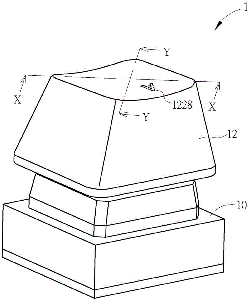
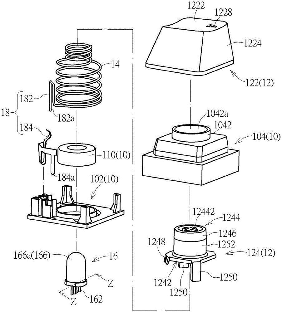
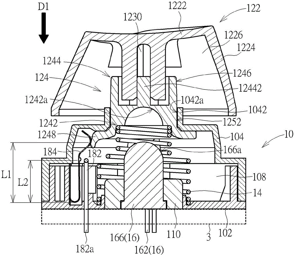
[0033] see Figure 1 to Figure 4 . A light-emitting key structure 1 according to an embodiment of the present invention includes a base 10 , a keycap 12 , a restoring force mechanism 14 , a light source device 16 and a switch 18 . The keycap 12 is arranged on the base 10, and the restoring force mechanism 14 is arranged between the base 10 and the keycap 12, so that the keycap 12 is pushed away from the base 10 by the restoring force mechanism 14 in a direction D1 (shown by an arrow in the image 3 and Figure 4 middle) to move. Among them image 3 or Figure 4 In terms of viewing angle, the direction D1 is equivalent to the vertical direction. In this embodiment, the restoring force mechanism 14 is a spring, but the present invention is not limited thereto. Therefore, when the keycap 12 is pressed and moves toward the base 10 parallel to the direction D1, the restoring force mechanism 14 is also pressed to store the elastic potential energy; when the keycap 12 is no longer


PUM


Abstract

The invention discloses a flickering key structure which comprises a base, a keycap, a restoring force mechanism and a light source device, wherein the keycap comprises a cap body and a light guiding column; the restoring force mechanism is connected between the base and the light source device; the keycap can be vertically moved relative to the base under the driving of the restoring force mechanism; the light source device is arranged between the light guiding column and the base and is faced to the emitting light of the light guiding column. The light enters from one end of the light guiding column, and then is emitted to the cap body from the other end and the side surface surrounding the end of the light guiding column, so that the cap body is capable of wholly receiving the relative uniform backlight.

Description


Claims


Application Information

Patent Timeline
Owner DARFON ELECTRONICS (SUZHOU) CO LTD
Why Eureka
Try Eureka