Punching head structure for sheet metal punching

A punching head and punching technology, which is applied in the field of sheet metal processing, can solve the problems of low hole processing quality, affecting the quality of the plate, and many burrs on the edge of the hole, so as to reduce deformation, improve punching quality, and improve punching quality. speed effect

Inactive Publication Date: 2016-06-22
无锡市通协物资有限公司
View PDF6 Cites 0 Cited by
  • Summary
  • Abstract
  • Description
  • Claims
  • Application Information

AI Technical Summary

Benefits of technology

This new design allows for faster processing by combining two parts with different shapes that reduce bending or distortion during use without affecting their shape after being created. It achieves this through precise control over how these tools work together.

Problems solved by technology

This patented problem addressed in this patents relates to improving the accuracy and efficiency when drilling small parts during manufacturing processes such as machining tools used for electronic components. These existing methods have issues where tiny bits from cutting can cause damage to sensitive areas within the part being worked upon.

Method used


Image

  • Punching head structure for sheet metal punching

Examples


Embodiment Construction

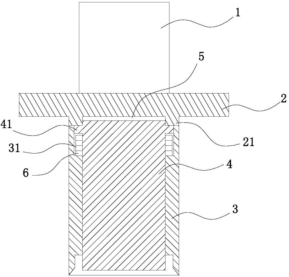
[0011] The specific implementation manner of the present invention will be described below in conjunction with the accompanying drawings.

[0012] See figure 1 , the present invention comprises a punching driving device 1, an upper template 2 and a punching head 3, the punching driving device 1 drives the upper template 2 to drive the punching head 3 to reciprocate up and down; the punching head 3 is equipped with a punch 4, punching The inner side wall of the upper end of the head 3 is symmetrically provided with a chute 31, and the chute 31 is slidably connected with the slider 41 on the outer wall of the upper end of the punch 4. The multilayer buffer pad 6 is respectively installed in the chute 31, and the upper and lower sides of the multilayer buffer pad 6 The two ends are respectively close to the bottom surface of the slider 41 and the chute 31; the punch 4 is staggered in the punching head 3, that is, the lower end surface and the upper end surface of the punching head 4


PUM


Abstract

The invention relates to a punching head structure for sheet metal punching processing, which comprises a punching driving device, an upper template and a punching head. The chute is slidably connected to the slider on the outer wall of the upper end of the punch, and the chute is respectively equipped with a multi-layer buffer pad; the lower end face and the upper end face of the punch head are respectively higher than the lower end face and the upper end face of the punching head On the end face, there is a buffer gap between the upper end face of the punch and the upper template; the lower surface of the upper template is provided with a convex ring abutting against the upper end face of the punching head. The structure of the invention is exquisite, and the punch is combined with the punching head, which not only improves the punching speed, but also reduces the deformation of the workpiece, improves the punching quality, and can prevent the workpiece from being stuck on the punching head. Finish punching.

Description


Claims


Application Information

Patent Timeline
Owner 无锡市通协物资有限公司
Why Eureka
Try Eureka