Grid frequency response

A technology of frequency response and grid frequency, applied in wind power generation, photovoltaic power generation, electrical components, etc.

Active Publication Date: 2016-06-22
REACTIVE TECH
View PDF7 Cites 3 Cited by
  • Summary
  • Abstract
  • Description
  • Claims
  • Application Information

AI Technical Summary

Problems solved by technology

This represents a delay in the determination of the frequency response characteristics; this makes it difficul

Method used


Image

  • Grid frequency response
  • Grid frequency response
  • Grid frequency response

Examples


example

[0207] refer to Figure 5 , shows an example method for determining the frequency response characteristics (eg, inertia or stiffness) of a specified region of an electrical grid at a specified time.

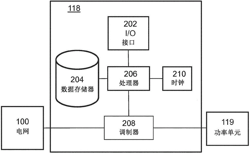
[0208] Figure 5 A power unit 119 is shown connected to a part of the synchronous grid 504 via a modulation device 118 . Modulation device 118 can be used with the Figure 2a The modulation setup is shown in the same, but in Figure 5 In , only data memory 204 and modulator 208 are shown for clarity. A code 502 is stored in the data memory 204 of the modulating device 118, assigned for use by the group of power units 119, and transmitted to the modulator 208 to generate a power modulation signal at the point where the modulating device is connected to the grid At point 506, the signal is added to the power flow of the remaining grid.

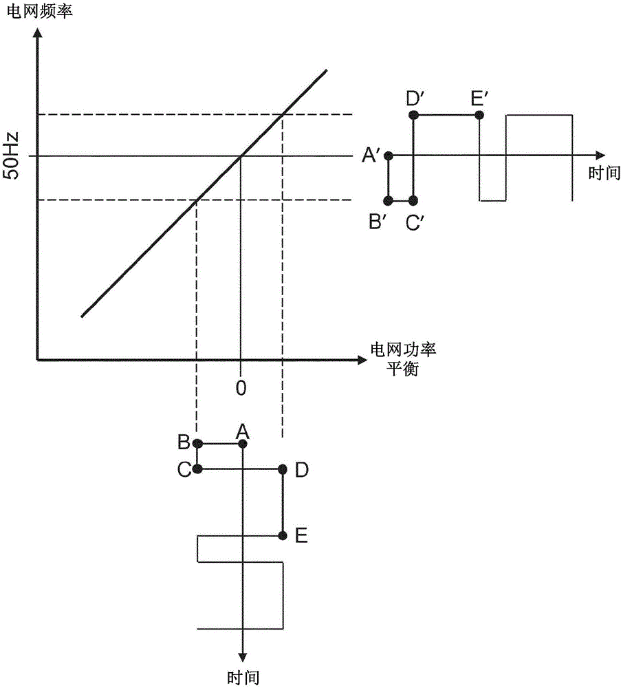
[0209] As mentioned above, power modulation causes a corresponding frequency modulation. These modulated signals propagate through the measurem


PUM


Abstract

Method and apparatus for determining inertia within a synchronous area of an electric power grid are described. Power flow to and/or from a group of one or more power units is modulated on the basis of a sequence of control signals (figure 4a) and a frequency characteristic relating to a frequency of electricity flowing in the electric power grid measured (solid lines of figures 4b-4d). A frequency response characteristic associated with at least one area of the electric power grid is determined on the basis of the measured frequency characteristic and the determined magnitude characteristic. From this it is determined whether the inertia in the area of the grid in which the power unit is located is low (figure 4b), medium (figure 4c) or high (figure 4d), and it enables frequency response characteristics within a synchronous area of the electric power grid to be easily determined.

Description


Claims


Application Information

Patent Timeline
Owner REACTIVE TECH
Why Eureka
Try Eureka