Rotary two-way shackle

A rotary and buckle technology, applied in the direction of transmission elements or pulley ropes or cables, textile cables, belts/chains/gears, etc., can solve the problem of low applicability and achieve a strong practical effect

Inactive Publication Date: 2016-07-06
CHONGQING RES BETTER SCI & TECH
View PDF0 Cites 1 Cited by
  • Summary
  • Abstract
  • Description
  • Claims
  • Application Information

AI Technical Summary

Problems solved by technology

Traditional shackles only have one buckle body, which is less suitable for some places where the stressed rope needs to be split. cannot meet the needs of its use

Method used


Image

  • Rotary two-way shackle
  • Rotary two-way shackle
  • Rotary two-way shackle

Examples


Example Embodiment

[0019] The present invention will be further explained below in conjunction with the drawings:

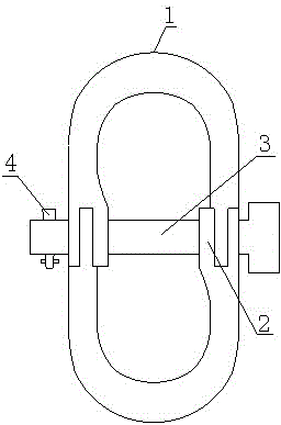
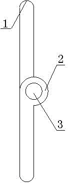
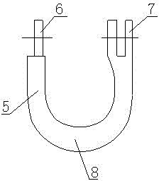
[0020] Such as figure 1 , figure 2 , image 3 with Figure 4 As shown, the rotary two-way shackle of the present invention includes a buckle body and an axle pin. The buckle body includes two single buckles 1. The single buckle 1 is a cylindrical U-shaped buckle. Both ends of the two single buckles 1 are provided with connecting rings 2 , The two connecting rings 2 are connected by a pin 3, the connecting ring 2 includes an outer ring 7 and an inner ring 6, the outer ring 7 includes two circular rings, and the outer ring 7 is fixedly connected to the first end of the single buckle 1 and two A gap is provided between the circular rings, and the inner ring 6 is fixedly connected to the second end of the single buckle 1. Both the outer ring 7 and the inner ring 6 are provided with a through hole 9 for passing through the pin shaft 3. The diameter is equal to the radius of the connecting r


PUM


Abstract

The invention discloses a rotary two-way shackle which comprises a shackle body and a hinge pin, wherein the shackle body comprises two single buckles; the single buckles are cylindrical U-shaped buckles; connecting rings are arranged at the two ends of the two single buckles; the two connecting rings are connected through the hinge pin; each connecting ring comprises an outer ring and an inner ring; each outer ring comprises two circular rings; each outer ring is fixedly connected with a first end of the corresponding single buckle; a clearance is arranged between the two circular rings; each inner ring is fixedly connected with a second end of the corresponding single buckle; and a through hole for allowing the hinge pin to pass through is formed in each of the outer rings and the inner rings. According to the rotary two-way shackle, the two rotary single buckles are connected through the hinge pin and the connecting rings, so that the rotary two-way shackle can be switched between a one-way shackle and a two-way shackle, can adapt to multiple practical environments, and is relatively high in practicability.

Description


Claims


Application Information

Patent Timeline
Owner CHONGQING RES BETTER SCI & TECH
Why Eureka
Try Eureka