Pressure reducing valve

A pressure reducing valve and valve body technology, applied in the field of pressure reducing valves, can solve the problems of inconvenient installation and maintenance of valves, achieve the effect of preventing fluid backflow and prolonging service life

Inactive Publication Date: 2016-07-20
TIANJIN SHOUFA TECH CO LTD
View PDF0 Cites 0 Cited by
  • Summary
  • Abstract
  • Description
  • Claims
  • Application Information

AI Technical Summary

Problems solved by technology

Existing pressure reducing valves often require various valves to be used together, which causes a lot of inconvenience to the installation and main

Method used


Image

  • Pressure reducing valve

Examples


Embodiment Construction

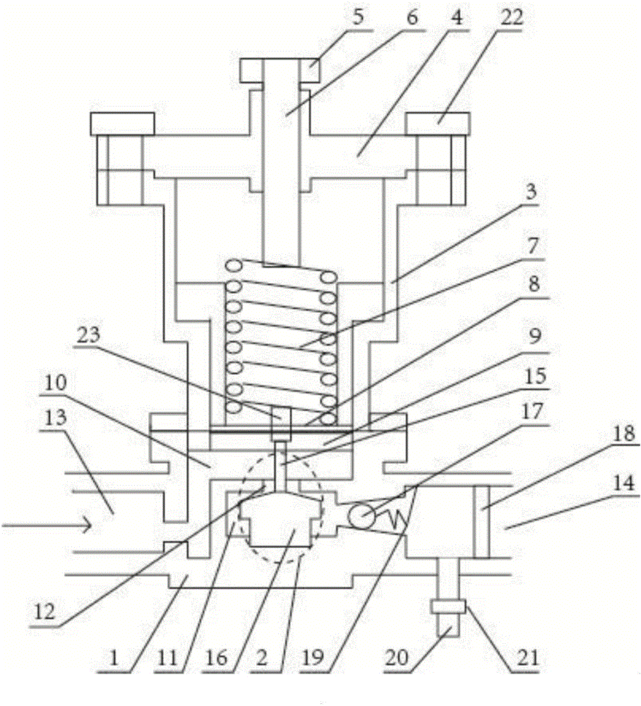
[0020] The specific implementation manners of the present invention will be briefly described below in conjunction with the accompanying drawings.

[0021] Such as figure 1 A pressure reducing valve shown includes a valve body 1, a valve core 2, an upper valve cover 3, a cover plate 4, an adjusting bolt 5, an adjusting column 6, an adjusting spring 7, a sealing cover 8, and a sealing body 9; the valve body 1 There is an upper valve chamber 10 and a lower valve chamber 11 inside, the upper valve chamber 10 penetrates the upper end of the valve body 1, the lower valve chamber 11 penetrates the lower end of the valve body 1, and a valve chamber 10 and the lower valve chamber 11 are provided Control hole 12, the two sides of valve body 1 are provided with water inlet 13 and water outlet 14, and water inlet 13 communicates with upper valve chamber 10, and water outlet 14 communicates with lower valve chamber 11, and described sealing cover 8, sealing body 9 are positioned at The uppe


PUM


Abstract

The invention relates to a pressure reducing valve. The pressure reducing valve comprises a valve body, a valve element, an upper bonnet, a cover plate, a regulating bolt, a regulating post, a regulating spring, a sealing cover and a sealing body, wherein the inner part of the valve body is provided with an upper valve chamber and a lower valve chamber; a control hole is formed between the upper valve chamber and the lower valve chamber; the two sides of the valve body are provided with a water inlet and a water outlet; the water inlet communicates with the upper valve chamber; the water outlet communicates with the lower valve chamber; the sealing cover and the sealing body are positioned on the upper end part of the valve body; the regulating spring is positioned in the upper bonnet; the sealing body is arranged in the upper valve chamber; the valve element comprises a guide post and a tapered plug; a water outlet pipeline is gradually thickened in a tapered manner, and a blocking ball and a filter element are sequentially arranged in the pipeline; the blocking ball is fixedly arranged in the pipeline through a spring; a sewage discharge pipeline is arranged on the pipeline between the blocking ball and the filter element; and a stop valve is arranged on the sewage discharge pipeline. The pressure reducing valve has a pressure reducing function, and can filter a flow-through fluid and can prevent the fluid from flowing back.

Description


Claims


Application Information

Patent Timeline
Owner TIANJIN SHOUFA TECH CO LTD
Why Eureka
Try Eureka