Multi-frequency community antenna

A technology for sharing antennas and antennas, applied in the directions of antennas, antenna coupling, antenna arrays, etc., can solve problems such as unfavorable network optimization, boundary condition changes, and radiation index deterioration, and achieve the effect of facilitating network optimization.

Inactive Publication Date: 2016-07-20
CHINA TELECOM CORP LTD
View PDF3 Cites 2 Cited by
  • Summary
  • Abstract
  • Description
  • Claims
  • Application Information

AI Technical Summary

Benefits of technology

This patented technology allows multiple frequencies (or more) within range from one another to be used together without compromising their performance or requiring complicated equipment designing changes that may affect them differently depending on how much they are located inside buildings. It makes it easier than just having two separate radios at once - each with its own unique directional angle settings – allowing better control over signal quality based on specific areas where signals should go through.

Problems solved by technology

This patented technical problem addressed in this patents relates to improving wireless communications system design without sacrificing its ability to adaptively optimize signal reception based upon changes in location where signals may arrive from multiple sources such as buildings with varying elevational dimensions.

Method used


Image

  • Multi-frequency community antenna
  • Multi-frequency community antenna
  • Multi-frequency community antenna

Examples


Embodiment Construction

[0032] The following will clearly and completely describe the technical solutions in the embodiments of the present invention with reference to the accompanying drawings in the embodiments of the present invention. Obviously, the described embodiments are only some, not all, embodiments of the present invention. The following description of at least one exemplary embodiment is merely illustrative in nature and in no way taken as limiting the invention, its application or uses. Based on the embodiments of the present invention, all other embodiments obtained by persons of ordinary skill in the art without creative efforts fall within the protection scope of the present invention.

[0033] The relative arrangements of components and steps, numerical expressions and numerical values ​​set forth in these embodiments do not limit the scope of the present invention unless specifically stated otherwise.

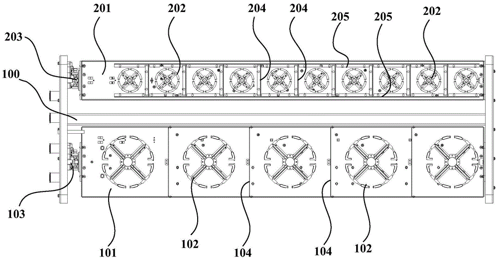
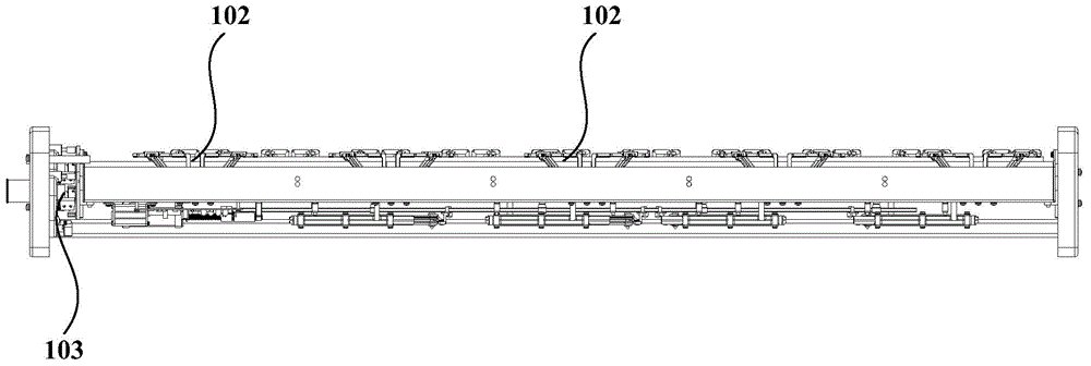
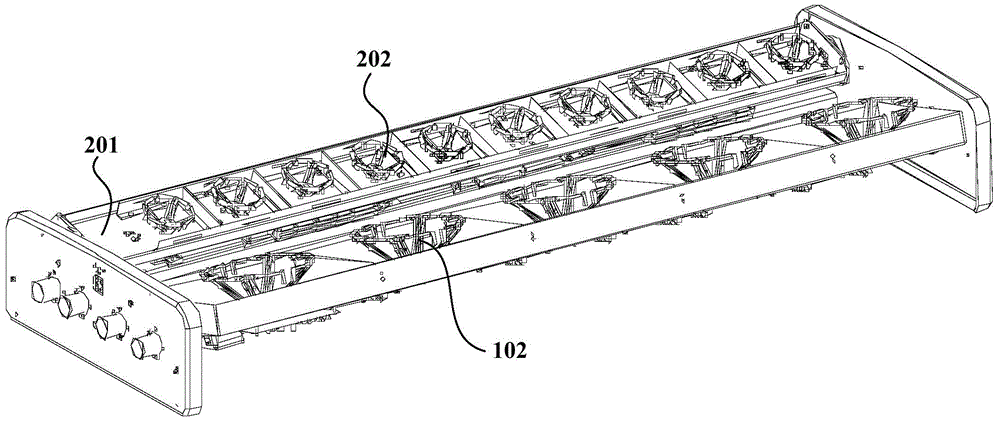
[0034] The invention provides a multi-frequency shared antenna, which includes a s


PUM


Abstract

The invention discloses a multi-frequency community antenna. The antenna comprises a support frame and at least two base plates, wherein radiation units of corresponding frequencies are arranged on each base plate, thus forming a radiation array; and horizontal azimuths of the base plates can be independently adjusted. According to the multi-frequency community antenna, the horizontal azimuths of antennas of different frequencies can be flexibly and independently adjusted according to coverage regions, therefore, network optimization is convenient.

Description


Claims


Application Information

Patent Timeline
Owner CHINA TELECOM CORP LTD
Why Eureka
Try Eureka