High-rise escape safety device

A safety device and high-rise technology, applied in the field of high-rise escape devices, can solve the problems of inability to meet the needs of high-rise rescue, unsuitable for the elderly and infants, and inconvenient to operate, and achieve a simple structure, increased friction devices, and high reliability. Effect

Inactive Publication Date: 2016-08-10
MAANSHAN XIANGYU MACHINERY AUTOMATION SCI & TECH
View PDF3 Cites 0 Cited by
  • Summary
  • Abstract
  • Description
  • Claims
  • Application Information

AI Technical Summary

Benefits of technology

The technical effect described in this patented technology relates to an improved safety system for buildings that uses less expensive components than traditional methods like springs or hydraulic systems. It also improves its durability over time because it does away with regular maintenance.

Problems solved by technology

This patented technical problem addressed in this patents relates to improving the design of conventional building evacuation systems used during fires or other situations that may cause damage due to lack of space available when they shouldn't be safe from exiting them quickly enough after it has been done.

Method used


Image

  • High-rise escape safety device
  • High-rise escape safety device
  • High-rise escape safety device

Examples


Embodiment Construction

[0016] The present invention will be further described below in conjunction with the accompanying drawings.

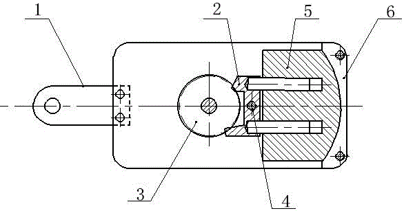
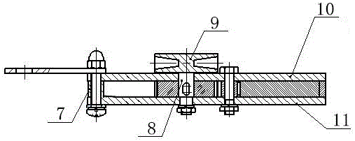
[0017] In the figure, the high-rise escape safety device is mainly composed of a hook 1, a swing claw 2, a rotating gear 3, a swing claw shaft 4, an upper friction plate 5, a lower friction plate 6, a sleeve 7, a sheave shaft 8, a sheave 9, and an upper plate. 10 and base plate 11 constitute.

[0018] The swing mechanism and the friction device are assembled between the upper plate 10 and the bottom plate 11, the swing mechanism includes a rotating gear 3 and a swing claw 2, and the rotating gear 3 is assembled on the upper plate 10 and the bottom plate through a sheave shaft 8 Between 11, the rotating gear 3 is connected with the sheave shaft 8, and the sheave shaft 8 passes through the shaft holes of the upper plate 10 and the bottom plate 11, and the sheave 9 is fixedly connected with the sheave shaft 8, and the sheave 9 is on the upper plate 10, the swing claw 2 is a


PUM


Abstract

The invention discloses a high-rise escape safety device, and belongs to the field of fire protection and lifesaving emergency equipment. The high-rise escape safety device is simple in structure, high in reliability, easy to operate and free of external energy resources. The high-rise escape safety device comprises a rope wheel, an upper plate, a base plate, a swing mechanism and a friction device, the swing mechanism and the friction device are assembled between the upper plate and the base plate, and a sleeve and a hook are assembled between the upper plate and the base plate. The high-rise escape safety device is suitable for any-layer high-rises; potential energy can be converted into kinetic energy by additionally arranging the swing mechanism; meanwhile, the mass of an upper friction plate is increased, so that the falling speed is decreased; and the friction device is additionally arranged, so that the speed is decreased by increasing the friction force.

Description


Claims


Application Information

Patent Timeline
Owner MAANSHAN XIANGYU MACHINERY AUTOMATION SCI & TECH
Why Eureka
Try Eureka