Dephosphorization wheel shaft

A wheel shaft and bearing seat technology, applied in the direction of grinding machines, grinding machine parts, metal processing equipment, etc., can solve the problems of easily damaged and dephosphorized wheel shaft precious parts, troublesome disassembly and maintenance, time-consuming and labor-intensive problems, and achieve easy maintenance and maintenance , Simple and compact structure, the effect of improving work efficiency

Inactive Publication Date: 2016-09-28
ZHENJIANG NAISI ADVANCE MATERIALS
View PDF8 Cites 2 Cited by
  • Summary
  • Abstract
  • Description
  • Claims
  • Application Information

AI Technical Summary

Benefits of technology

The new design for this type of device allows it to be quickly assembled without having any extra parts or tools needed during assembly process. This makes installation easier than previous designs that had complicated threads at both ends.

Problems solved by technology

Technological Problem: Metal materials used in manufacturing processes require that they have high purity levels without any impurities like oxygen (O2) present therein before being processed into products made from them. However, current methods involve removing unwanted layers called rusts over time due to poor designing and assembly issues caused by previous designs. Additionally, these technical problem addressed in the patented solution involves maintaining effective cleanliness while preventing damaging important components within the device's interior.

Method used


Image

  • Dephosphorization wheel shaft

Examples


Embodiment Construction

[0014] The present invention will be further explained below in conjunction with the accompanying drawings and specific embodiments.

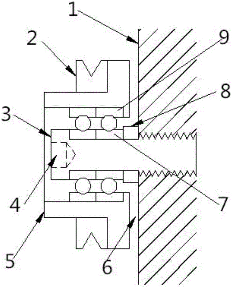
[0015] Such as figure 1 As shown, the phosphorus removal wheel shaft includes a base 1, an alloy ring 2, a phosphorus removal shaft 3, an inner hexagon thread 4, a bearing seat 5, a gap 6, an inner steel ring 7, a spacer ring 8 and an outer steel ring 9.

[0016] One end of the dephosphorization shaft 3 is threaded and installed on the base 1 , and the other end of the dephosphorization shaft 3 is provided with an inner hexagon thread 4 . An inner steel ring 7 and an outer steel ring 9 are sequentially arranged on the outer periphery of the phosphorus removal shaft 3 . A bearing seat 5 is arranged on the outer side of the outer steel ring 9, and an alloy ring 3 is arranged on the bearing seat 5. A gap 6 is reserved between the dephosphorization shaft 3 and the base 1 , and a spacer 8 is provided between the inner steel ring 7 on the dephosphoriz


PUM


Abstract

The invention discloses a dephosphorization wheel shaft, and belongs to the technical field of metal wire production. The dephosphorization wheel shaft comprises a dephosphorization shaft, wherein one end of the dephosphorization shaft is provided with threads and is mounted on a base; and the other end of the dephosphorization shaft is provided with inner hexagonal threads. According to the dephosphorization wheel shaft, one end of the dephosphorization shaft is provided with the threads and is mounted on the base, and the other end of the dephosphorization shaft is provided with the inner hexagonal threads, so that the dephosphorization wheel shaft is simple and compact in structure, and is quickly dismounted, and therefore, working efficiency is improved, and repair and maintenance are easy.

Description


Claims


Application Information

Patent Timeline
Owner ZHENJIANG NAISI ADVANCE MATERIALS
Why Eureka
Try Eureka