Touch control detection mechanism

A detection mechanism and touch technology, which is applied in the direction of measuring electricity, measuring devices, measuring electrical variables, etc., can solve the problems of poor sensitivity of the touch panel, too sensitive sensitivity, high requirements for testing personnel, etc., and achieve the effect of improving authenticity

Inactive Publication Date: 2016-10-12
SUZHOU SECOTE PRECISION ELECTRONICS CO LTD
View PDF11 Cites 0 Cited by
  • Summary
  • Abstract
  • Description
  • Claims
  • Application Information

AI Technical Summary

Problems solved by technology

[0003] The use of touch includes the effect of using the touchpad. If the sensitivity of the touchpad (that is, the touch screen) is poor or too sensitive, the user's use effect will be greatly reduced.
[0004] For this reason, before the tablet computer leaves the factory, it is required to detect whether the touch screen of the tablet computer is qualified. In the prior art, a vertic

Method used


Image

  • Touch control detection mechanism

Examples


Example Embodiment

[0022] In order for those skilled in the art to better understand the technical solutions of the present invention, the technical solutions of the present invention are further described below with reference to the accompanying drawings and through specific embodiments.

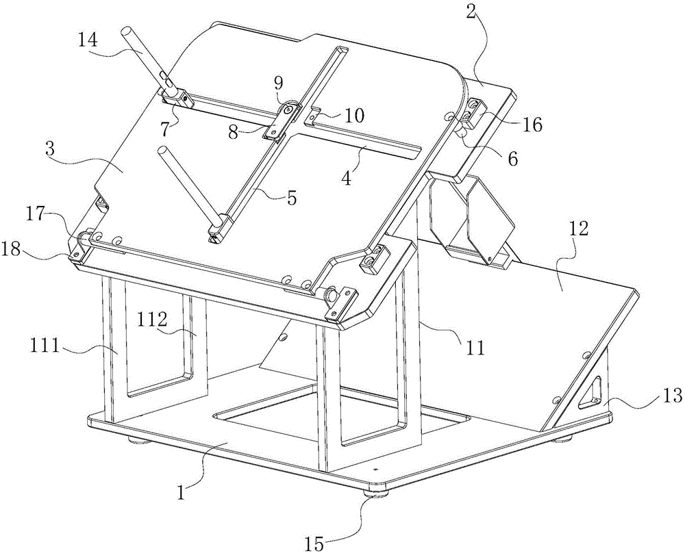
[0023] In this embodiment, a touch detection mechanism is provided to assist the detection personnel to detect the computer touch screen, such as figure 1 As shown, the mechanism includes a bracket 1, a carrier plate 2, and a cover plate 3, the carrier plate 2 is obliquely arranged on the bracket 1, the cover plate 3 and the carrier plate 2 are movably connected, and the cover plate 2 is movably connected. 3 is provided with a horizontal chute 4 and a vertical chute 5, and both the horizontal chute 4 and the vertical chute 5 are provided with a slidable stylus 14; the horizontal chute 4 and the The vertical chute 5 is in vertical communication, and a limiting mechanism is provided at the connection between the h


PUM


Abstract

The invention relates to the technical field of electronic product detection, in particular to a touch detection mechanism for detecting a touch screen of a tablet computer. It includes a bracket, a carrier plate and a cover plate. The carrier plate is arranged obliquely on the bracket. The cover plate and the carrier plate are movably connected. The cover plate is provided with a horizontal chute and a vertical chute. A slidable stylus is arranged in the grooves; a limiting mechanism is arranged at the connection between the horizontal chute and the vertical chute. In the present invention, a horizontal chute and a vertical chute are arranged on the cover plate, so that the stylus can slide along the horizontal chute and the vertical chute, thereby ensuring that the drawn line is a straight line without bending problems. At the same time, a limit mechanism is provided at the connection between the horizontal chute and the vertical chute, which can prevent the stylus from running into another chute during the marking process. The detection mechanism effectively assists the detection personnel to detect the screen of the tablet computer, and improves the authenticity of the detection result.

Description


Claims


Application Information

Patent Timeline
Owner SUZHOU SECOTE PRECISION ELECTRONICS CO LTD
Why Eureka
Try Eureka