High-pressure jet water face operating device

A kind of operation equipment and high-pressure jet technology, which is applied in the field of high-pressure jet water surface operation equipment, can solve the problems of low efficiency and achieve the effect of improving operation efficiency

Inactive Publication Date: 2016-11-09
沈阳凤天机器人科技有限公司
View PDF6 Cites 1 Cited by
  • Summary
  • Abstract
  • Description
  • Claims
  • Application Information

AI Technical Summary

Benefits of technology

This technology allows for easy connection between different parts on an operating table by means of buttons or switches instead of manually controlling them with hands alone. It improves work efficacy compared to traditional methods like button press controls.

Problems solved by technology

The technical problem addressed in this patented text relates to increasing efficient use for certain applications by providing multiple cut points at once without sacrificing performance or requiring more complex machinery that requires higher costs than usual.

Method used


Image

  • High-pressure jet water face operating device
  • High-pressure jet water face operating device

Examples


Embodiment Construction

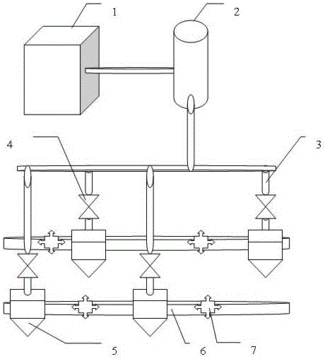
[0016] Attached below figure 1 Examples further illustrate the present invention

[0017] The present invention is an equipment combination of a distributed equipment operation system. The high-pressure water generator (1) generates the high-pressure water required for work, and stores it in the high-pressure water storage device (2) through a controllable pipeline. Automatic or manual control The high-pressure water control valve (4) makes the high-pressure water in the high-pressure water storage (2) reach the high-pressure water cutting head (5) by connecting the controllable pipelines and connecting pipes (3) of each section, and is sprayed by the nozzle. The high-speed, high-pressure jet water shoots to the working point to achieve the purpose of the operation.

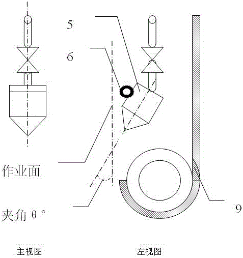
[0018] The high-pressure water cutting head (5) and force balancer (7) are distributed on the connector (6) in an array, and are given corresponding working positions and postures to maintain an appropriate distanc


PUM


Abstract

The present invention relates to an application device of a high-pressure jet water cutting technique, which allows maximum improvement of the efficiency of the high-pressure jet water cutting operation and achievement of significant economical benefits in high efficiency. At present, all well-known high-pressure jet water cutting application devices operate in a single-cutting point movement pattern in low efficiency, and can only meet the requirements of some high-end users. In the present invention, an existing mature high-pressure jet water production device and a high-pressure water storage device are combined into a device for concentrated supply of high-pressure water that is further provided with cutting heads capable of operating movably and distributed in an array and corresponding automatic control valves thereof; under the control of a central controller, the operating pattern of each cutting head can be selectively controlled, such that multi-point simultaneous cutting is achieved to form an operating face; besides, mobile operation is allowed such that the operating face can be enlarged continuously.

Description


Claims


Application Information

Patent Timeline
Owner 沈阳凤天机器人科技有限公司
Why Eureka
Try Eureka