Working temperature display method and device of switch

A technology of working temperature and display method, applied in the network field, can solve the problem of unintuitive viewing method of working temperature, and achieve the effect of improving acquisition efficiency

Inactive Publication Date: 2016-11-09
SHENZHEN ALLWINS TECH
View PDF4 Cites 1 Cited by
  • Summary
  • Abstract
  • Description
  • Claims
  • Application Information

AI Technical Summary

Benefits of technology

The technical effect of this innovation allows users to easily see how well their switch works by showing it with different colors on its surface. This helps them get an accurate understanding about what they are doing at that particular moment or over time.

Problems solved by technology

The technical problem addressed in this patented method for controlling the cooler used with electronic devices such as mobile phones has been that users have difficulty accurately monitoring their temperatures during use due to increased energy usage caused by increasingly high-temperature environments like smartphones.

Method used


Image

  • Working temperature display method and device of switch
  • Working temperature display method and device of switch
  • Working temperature display method and device of switch

Examples


Embodiment Construction

[0018] In the following description, specific details such as specific system structures and technologies are presented for the purpose of illustration rather than limitation, so as to thoroughly understand the embodiments of the present invention. It will be apparent, however, to one skilled in the art that the invention may be practiced in other embodiments without these specific details. In other instances, detailed descriptions of well-known systems, devices, circuits, and methods are omitted so as not to obscure the description of the present invention with unnecessary detail.

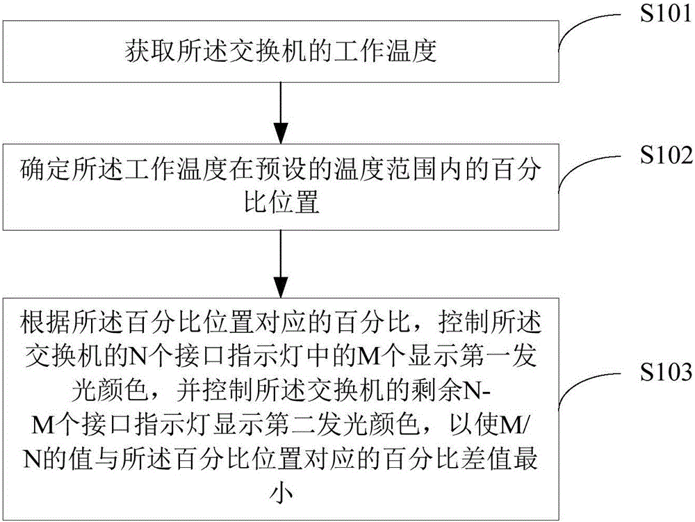
[0019] In the embodiment of the present invention, the operating temperature of the switch is obtained; the percentage position of the operating temperature within a preset temperature range is determined; and the N interface indicator lights of the switch are controlled according to the percentage corresponding to the percentage position M of them display the first luminous color, and control the re


PUM


Abstract

The invention is suitable for the field of the network technology, and provides a working temperature display method and device of a switch. The method comprises the following steps: obtaining the working temperature of the switch; determining the percent position of the working temperature in a preset temperature range; and according to a percent corresponding to the percent position, controlling M interface indicator lights in the N interface indicator lights of the switch to display a first luminescence color, and controlling the residual (N-M) interface indicator lights of the switch to display a second luminescence color to cause difference value between a M/N value and a percent corresponding to the percent position to be minimum. In the method, a user can intuitively know the working temperature situation of the switch through the luminescence color display situation of the interface indicator light of the switch, and the acquisition efficiency of the working temperature information of the switch is improved.

Description


Claims


Application Information

Patent Timeline
Owner SHENZHEN ALLWINS TECH
Why Eureka
Try Eureka