Motion controller

A motion controller and ARM processor technology, applied in the direction of program control, computer control, comprehensive factory control, etc., can solve problems affecting the reliability of system hardware and few peripherals, shorten the development cycle, simplify hardware design, improve reliability effect

Inactive Publication Date: 2016-12-14
CHENGDU FUYU TECH
View PDF6 Cites 0 Cited by
  • Summary
  • Abstract
  • Description
  • Claims
  • Application Information

AI Technical Summary

Benefits of technology

This technology allows for better control over movement between two devices by allowing them to communicate through wireless networks or wired connections instead of relying solely upon their own physical connection capabilities. It also uses specialized cores that can be customizable based on various industries' demands. Overall, this innovation makes manufacturing faster and more efficient than previous methods due to its ability to optimize both hardware components and software designs.

Problems solved by technology

This patented technology solves issues in existing automatic controlling systems by providing more versatile options than just having specific types of input/output (I/O) connections available on their own chips or external components like routers.

Method used


Image

  • Motion controller
  • Motion controller

Examples


Embodiment Construction

[0018] The present invention will be further described in detail below in combination with specific embodiments. However, it should not be understood that the scope of the above subject matter of the present invention is limited to the following embodiments, and all technologies realized based on the content of the present invention belong to the scope of the present invention.

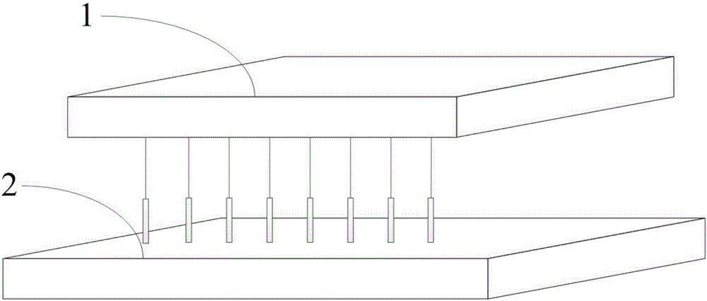
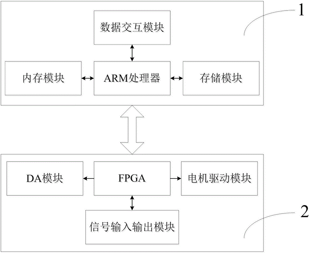
[0019] combine figure 1 and figure 2 The schematic diagram of the installation of the Core board and the MC board of the present invention and the connection schematic diagram of each module on the Core board and the MC board are shown respectively; wherein, the motion controller of the present invention includes a Core board, an MC board and a power supply module, wherein the Core board 1 is inserted On MC board 2, the power module provides corresponding voltages for Core board 1 and MC board 2 respectively; Core board 1 includes ARM processor, memory module, storage module and data interaction module


PUM


Abstract

The invention discloses a motion controller which comprises a Core board, an MC board and a power supply module, wherein the Core board is mounted on the MC board in an insertion manner. The power supply module supplies corresponding voltages to the Core board and the MC board. The Core board comprises an ARM process, a memory module, a storage module and a data exchange module. The MC board comprises an FPGA, a DA module, a motor driving module and a signal input/output module. The motion controller aims at requirements of specific devices in different industrial fields. Only adjustment on the hardware of the MC board is required, and adjustment on the hardware of the Core board is not required. A development period of a product is shortened. Furthermore the ARM processor is utilized on the Core board. Because the ARM has peripheral resources such as USB, serial ports and network ports, outer expansion of a corresponding interface chip is not required, thereby simplifying hardware design and improving system hardware reliability.

Description


Claims


Application Information

Patent Timeline
Owner CHENGDU FUYU TECH
Why Eureka
Try Eureka