Chlorine dioxide generating unit and chlorine dioxide generating device
A chlorine dioxide generation device technology, applied in the chlorine dioxide generation unit and chlorine dioxide generation device, vehicles or other vehicles, can solve the lack of chlorine dioxide continuity, main components or waste liquid leakage, etc. question
- Summary
- Abstract
- Description
- Claims
- Application Information
AI Technical Summary
Benefits of technology
Problems solved by technology
Method used
Image
Examples
Embodiment 1
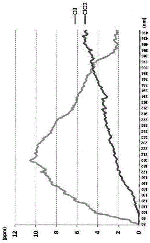
[0126] Example 1: Changes in the amount of chlorine dioxide produced by the wavelength of irradiated light
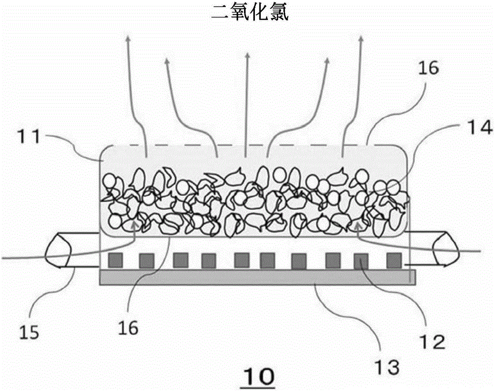
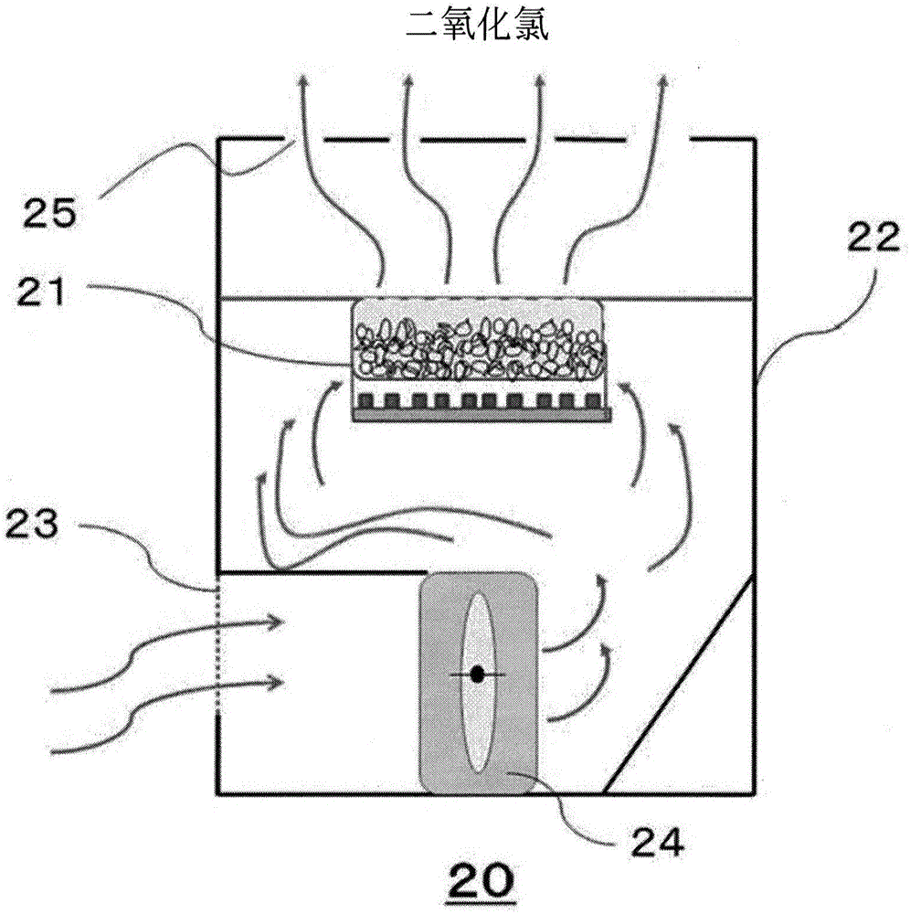
[0127] In this example, the use of figure 1 and figure 2 The chlorine dioxide generating unit and the chlorine dioxide generating device are tested.
[0128] figure 1 It is a longitudinal cross-sectional view showing the internal structure of the chemical storage part and the light source part of the unit for chlorine dioxide generation used in this Example. like figure 1 As shown, the chlorine dioxide generation unit 10 includes a chemical storage unit 11 and a light source unit (LED chip 12 and operation board 13 ) that generates light in the visible region. The drug container 11 contains a test drug 14 . The medicine container 11 is provided with an opening 16 so that air can move inside and outside. The unit 10 for chlorine dioxide generation is equipped with the pipe 15 which introduce|transduces the air outside an apparatus into an apparatus.
[0129] The
Embodiment 2
[0138] Example 2: Changes in the amount of chlorine dioxide produced by the shape of the catalyst
[0139] In sample 1 used in this example, except for using granular titanium dioxide (prepared by subjecting titanium to sintering treatment), the chemical agent was prepared in the same manner as in Example 1. In samples 2 and 3 used in this example, the same method as in example 1 was used to prepare the drug.
[0140] The medicines (samples 1 to 3) prepared by the above method were housed in the medicine storage parts of the chlorine dioxide generator described in Example 1, respectively. For Sample 1 and Sample 2, air was introduced into the device at 1 L / min from the opening of the drug container, and light of 405 nm was irradiated from the LED chip of the light source. For Sample 3, only air was introduced into the device at 1 L / min from the opening of the drug container, and light was not irradiated. Then, the concentration of chlorine dioxide contained in the air disch
Embodiment 3
[0142] Example 3: Discussion on the content ratio of chlorite and titanium dioxide in chemicals
[0143] 70 g of a 10 wt % sodium chlorite aqueous solution was spray-adsorbed on 100 g of sepiolite and dried, and then 20 g of a 10 wt % sodium hydroxide aqueous solution was spray-adsorbed and dried. Then, the amount of powdery titanium dioxide was changed and mixed therein to constitute the test agent used in this example. Irradiation of visible light to the test chemical was performed with the same chlorine dioxide generator and irradiation method as in Example 1.
[0144] Image 6 It shows the change of the chlorine dioxide generation amount when changing the ratio of the chlorite and titanium dioxide in the composition of this invention. Image 6 The relationship between the titanium dioxide content (wt%) in the chemical agent, the mass ratio of chlorite and titanium dioxide in the chemical agent, and the chlorine dioxide concentration (ppm) contained in the air 1 hour after t
PUM
 Abstract
Description
Claims
Application Information
 - R&D Engineer
- R&D Manager
- IP Professional
- Industry Leading Data Capabilities
- Powerful AI technology
- Patent DNA Extraction
Browse by: Latest US Patents, China's latest patents, Technical Efficacy Thesaurus, Application Domain, Technology Topic.
© 2024 PatSnap. All rights reserved.Legal|Privacy policy|Modern Slavery Act Transparency Statement|Sitemap


