Power factor correction circuit

A power factor correction and circuit technology, which is applied in output power conversion devices, electrical components, high-efficiency power electronic conversion, etc. problems, to achieve the effect of improving work efficiency

Inactive Publication Date: 2016-12-21
NINGBO SDIAPER OPTOELECTRONICS
View PDF2 Cites 4 Cited by
  • Summary
  • Abstract
  • Description
  • Claims
  • Application Information

AI Technical Summary

Problems solved by technology

[0003] However, in high-power occasions, the factors that affect the circuit efficiency are: 1) Since all semiconductor devices work in the hard switching mode, the switching loss is large; especially when it works in the state of continuous inductor current (CCM), the freewheeling diode The hard switch of the existing reverse recovery problem
As the output voltage and switching frequency increase, the loss caused by the reverse recovery current becomes larger, and the electromagnetic noise is also very serious; 2) At any time, there are always three semiconductor devices that are turned on

Method used


Image

  • Power factor correction circuit
  • Power factor correction circuit
  • Power factor correction circuit

Examples


Embodiment Construction

[0053] The following will clearly and completely describe the technical solutions in the embodiments of the present invention with reference to the accompanying drawings in the embodiments of the present invention. Obviously, the described embodiments are only some of the embodiments of the present invention, not all of them. Based on the embodiments of the present invention, all other embodiments obtained by persons of ordinary skill in the art without making creative efforts belong to the protection scope of the present invention.

[0054] It should be noted that, in the case of no conflict, the embodiments of the present invention and the features in the embodiments can be combined with each other.

[0055] The present invention will be further described below in conjunction with the accompanying drawings and specific embodiments, but not as a limitation of the present invention.

[0056] The present invention is based on the following findings:

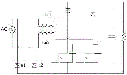
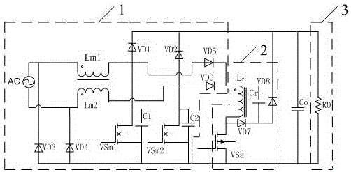
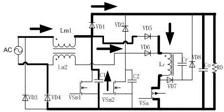
[0057] Such as figure 1The


PUM


Abstract

The invention discloses a power factor correction circuit. The power factor correction circuit comprises a rectifier circuit, a boost conversion circuit and a load circuit. The rectifier circuit is used for converting an alternating-current voltage into a direct-current voltage. The rectifier circuit comprises a first output end, a second output end and a third output end. The boost conversion circuit is used for boosting the direct-current voltage and outputting the direct-current voltage. The boost conversion circuit comprises a first input end, a second input end and a fourth output end. The fourth output end of the boost conversion circuit is connected with the first output end of the rectifier circuit. The first input end is connected with the second output end. The second input end is connected with the third output end. The load circuit is connected in series between the first output end of the rectifier circuit and the third output end. According to the technical scheme of the invention, the correction of the power factor is realized by adopting the boost conversion circuit, while the working efficiency is improved at the same time. The power factor value reaches more than 99%.

Description


Claims


Application Information

Patent Timeline
Owner NINGBO SDIAPER OPTOELECTRONICS
Why Eureka
Try Eureka