Testing tool for testing working state of solenoid valve coil

A solenoid valve coil, working state technology, applied in the direction of measuring magnetic variables, indicating the existence of current/voltage, measuring devices, etc., can solve the problems of no intuitive basis, inconvenient use of instruments and meters, low efficiency, etc., to achieve the effect of convenient use

Inactive Publication Date: 2019-06-25
吴佳璇 +1
View PDF13 Cites 1 Cited by
  • Summary
  • Abstract
  • Description
  • Claims
  • Application Information

AI Technical Summary

Problems solved by technology

At the same time, solenoid valves are often used in working environments where the environment is harsh, the space is narrow, and power outages cannot be stopped, resulting in heavy maintenance tasks for industrial automation control equipment, a wide variety of tools and instruments, and inconvenient use of instruments and meters.
[0003] In the prior art, the testing tool for measuring the working state of the solenoid valve coil has the following disadvantages: 1) the screwdriver, the tester and the solenoid valve coil working state tester cannot

Method used


Image

  • Testing tool for testing working state of solenoid valve coil
  • Testing tool for testing working state of solenoid valve coil
  • Testing tool for testing working state of solenoid valve coil

Examples


Embodiment Construction

[0022] The present invention will be described below with reference to specific examples. Those skilled in the art can understand that these examples are only used to illustrate the present invention and do not limit the scope of the present invention in any way.

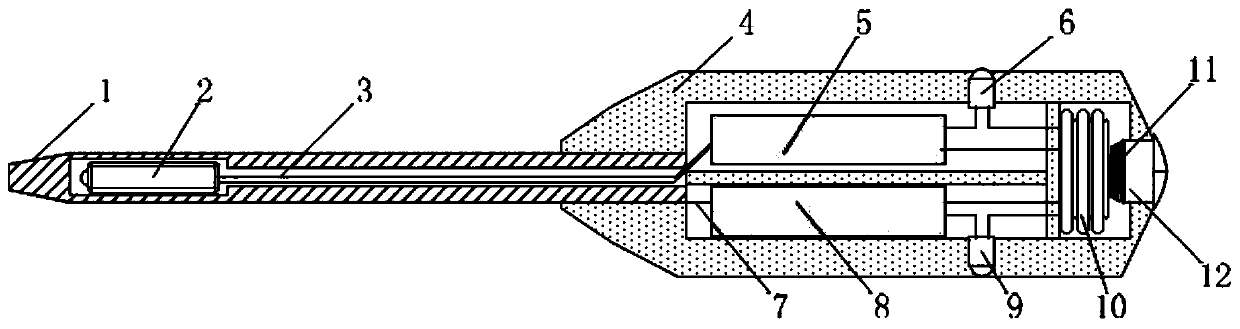
[0023] A test tool used to determine the working state of the solenoid valve coil, such as figure 1 As shown, it includes a screwdriver shaft (1), a miniature magnetic switch (2), an insulating handle (4), a solenoid valve coil working state test circuit, a test pencil circuit and a power supply assembly; the power supply part includes a button battery pack (10), a contact spring The sheet group (11) is located at the rear of the middle cavity of the insulating handle (4), and the battery can be replaced by unscrewing through the end cover (12). Preferably, the button battery pack (10) is composed of three button batteries.

[0024] Among them, one end of the screwdriver rod (1) is fixedly connected with the insulati


PUM


Abstract

The invention provides a testing tool for testing the working state of a solenoid valve coil, comprising a screwdriver rod, a micro magnetic switch, an insulating handle, a solenoid valve coil workingstate testing circuit, a test pencil circuit and a power assembly, wherein one end of the screwdriver rod is fixedly connected with the insulating handle and the other end is a screwdriver head for atest pencil test contact, the inner part has a hollow structure provided with the micro magnetic switch, and the hollow structure is communicated with the middle cavity of the insulating handle; andone part in the middle cavity of the insulating handle is the solenoid valve coil working state testing circuit which comprises an amplifying circuit and a solenoid valve working state indication light emitting diode, and the amplifying and load circuit is connected with the micro magnetic switch through a micro magnetic switch signal wire, and the other part is the test pencil circuit which comprises a test pen amplifying circuit, a current limiting resistor and a test pencil indication light emitting diode, and the screwdriver head as the test pencil test contact is connected with the test pen amplifying circuit and the current limiting resistor through a test pencil induction contact signal wire.

Description


Claims


Application Information

Patent Timeline
Owner 吴佳璇
Why Eureka
Try Eureka