Seat belt height adjuster
A height adjuster and safety belt technology, which is applied in the direction of seat belts, belt fixing devices, vehicle components, etc. in the car, can solve the problems of affecting user comfort and loud impact sound, so as to avoid impact sound and reduce impact sound amplitude , the effect of improving comfort
- Summary
- Abstract
- Description
- Claims
- Application Information
AI Technical Summary
Benefits of technology
Problems solved by technology
Method used
Image

Examples
Embodiment 1
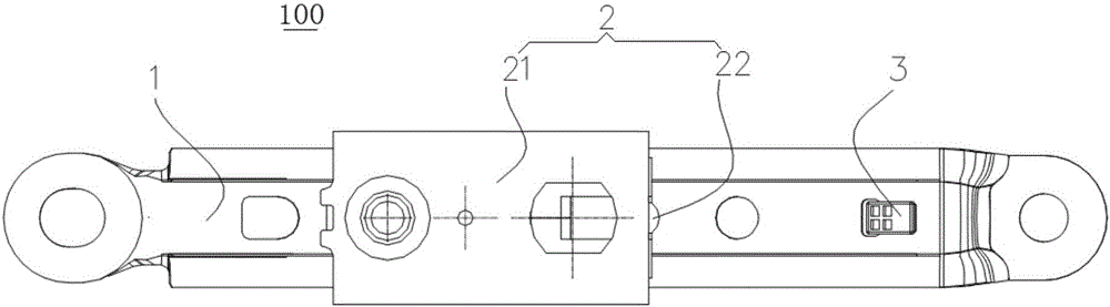
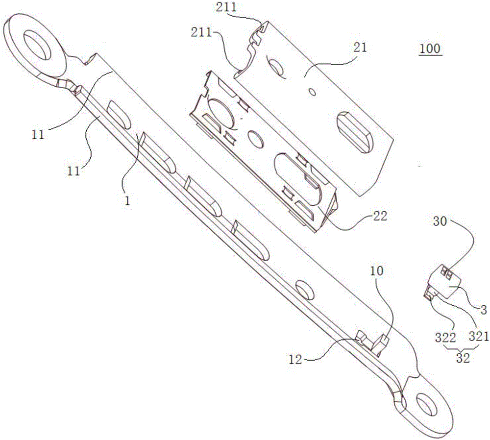
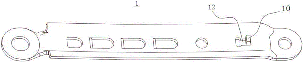
[0044] Such as Figure 1-Figure 6 As shown, the buffer member 3 and the stop member 10 are positioned by a positioning assembly, and the positioning assembly is used to prevent the buffer member 3 from separating from the stop member 10 in a direction parallel to the sliding surface of the slider assembly 2 . That is to say, the positioning assembly can prevent the buffer member 3 from moving parallel to the length direction of the installation frame 1 (for example figure 1 the left-right direction shown in ) and the width direction of the mounting bracket 1 (e.g. figure 1 The up and down direction shown in ) is separated from the stopper 10 on the plane defined, for example, the buffer 3 and the stopper 10 will not be separated in the length direction of the installation frame 1, and the buffer 3 and the stopper 10 will also be separated. There is no separation in the width direction of the mounting frame 1 . Therefore, by providing the positioning assembly, the buffer member
Embodiment 2
[0052] Such as Figure 7 As shown, the structure of the safety belt height adjuster 100A of the present embodiment is substantially the same as that of the safety belt height adjuster 100 of the first embodiment, wherein the same components use the same reference numerals, and the only difference is that in the first embodiment The fixing method of the buffer member 3 and the mounting frame 1 is different from that of the second embodiment.
[0053] refer to Figure 7 , the limit assembly includes: a limit ring 33 , the limit ring 33 is connected with the buffer member 3 and sleeved on the installation frame 1 . For example in Figure 7 In the example shown above, the limit ring 33 is generally formed in a "D" shape, one end of the limit ring 33 is connected to one side surface of the buffer member 3 in the width direction, and the other end of the limit ring 33 bypasses the mounting frame 1 and connects with the buffer The other side surface in the width direction of part 3 i
PUM
 Abstract
Description
Claims
Application Information
 - R&D Engineer
- R&D Manager
- IP Professional
- Industry Leading Data Capabilities
- Powerful AI technology
- Patent DNA Extraction
Browse by: Latest US Patents, China's latest patents, Technical Efficacy Thesaurus, Application Domain, Technology Topic.
© 2024 PatSnap. All rights reserved.Legal|Privacy policy|Modern Slavery Act Transparency Statement|Sitemap