A complementary metal oxide semiconductor controllable gain preamplification method and circuit

An oxide semiconductor, preamplifier circuit technology, applied in amplifiers with semiconductor devices/discharge tubes, amplifiers, gain control, etc. noise, improved reliability

Active Publication Date: 2011-06-01
INST OF ELECTRONICS CHINESE ACAD OF SCI
View PDF0 Cites 4 Cited by
  • Summary
  • Abstract
  • Description
  • Claims
  • Application Information

AI Technical Summary

Problems solved by technology

2.5mm×2.5mm×0.4mm, but the measurement circuit of the sensor still uses discrete devices, which are made of discrete devices
However, if such a large resistance is implemented with passive components in an integrated circuit, it will occupy phase
When the area is so large that it can be considered impossible to achieve

Method used


Image

  • A complementary metal oxide semiconductor controllable gain preamplification method and circuit
  • A complementary metal oxide semiconductor controllable gain preamplification method and circuit
  • A complementary metal oxide semiconductor controllable gain preamplification method and circuit

Examples


Example Embodiment

[0033] Example:

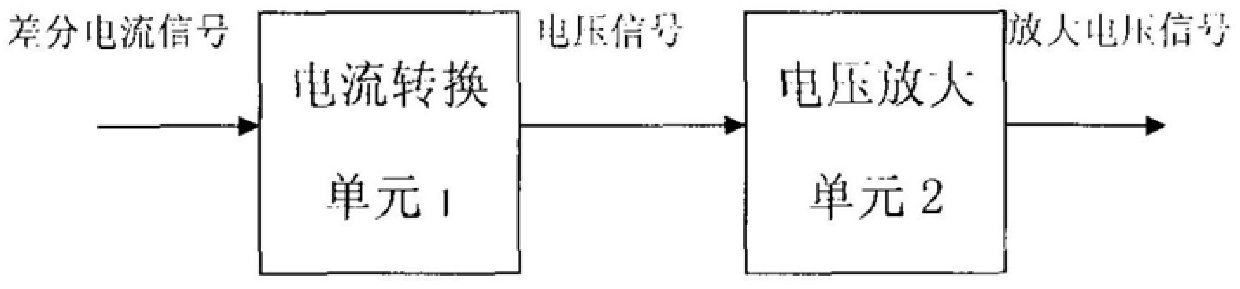
[0034] FIG. 1 is a block diagram of the preamplifier circuit of the present invention. The method of the present invention can be used by the current conversion circuit 1 and

The voltage amplifier circuit 2 is implemented.

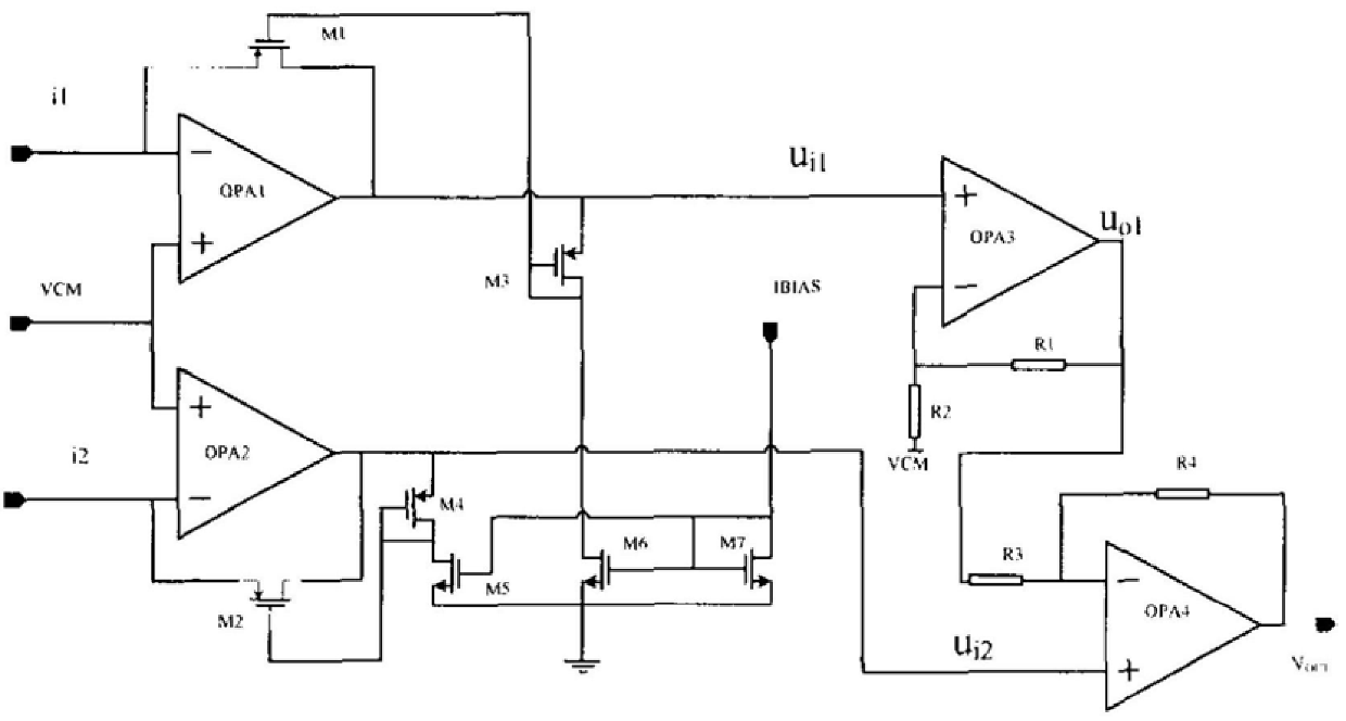
[0035] According to the present invention, FIG. 2 is the structure of the complementary metal oxide semiconductor controllable gain preamplifier circuit of the present invention.

Composition, including:

[0036] The current conversion unit 1, the voltage amplification unit 2, the two differential current signals output by the sensor are the first differential current

The current signal i1 and the second differential current signal i2 are fed into the current conversion unit 1 for converting the first differential current signal i1 and the second

The two differential current signal i2 is converted into a voltage signal, and the current conversion unit 1 outputs the voltage signal to the voltage amplifying unit 2.

To amplify the output voltage of


PUM


Abstract

The invention discloses a complementary metal oxide semiconductor controllable gain preamplification method and circuit of a miniature electric field sensor. The method is: on the complementary metal oxide semiconductor, use the long-channel transistor working in the linear region to realize the feedback resistance, and realize the control of the gain by adjusting the bias current to expand the input dynamic range of the current signal. Two-way differential signal amplification. The circuit includes: a current converting unit and a voltage amplifying unit. The invention can miniaturize the signal readout circuit of the miniature electric field sensor, and package it on the same substrate with the sensor, and even realize monolithic integration, greatly reduce the volume, weight and power consumption of the entire sensor system, and improve the sensor system. Reliability, the present invention has the advantages of miniaturization, low power consumption, low cost, high performance and intelligence.

Description


Claims


Application Information

Patent Timeline
Owner INST OF ELECTRONICS CHINESE ACAD OF SCI
Why Eureka
Try Eureka