Purification dehumidifier

A dehumidifier and air purification technology, used in mechanical equipment, heating methods, lighting and heating equipment, etc., can solve the problems of inability to purify air, inability to remove fine particles, dust removal, low utilization rate, etc., to improve utilization rate Effect

Inactive Publication Date: 2017-03-29
HISENSE HOME APPLIANCES GRP CO LTD +1
View PDF4 Cites 5 Cited by
  • Summary
  • Abstract
  • Description
  • Claims
  • Application Information

AI Technical Summary

Problems solved by technology

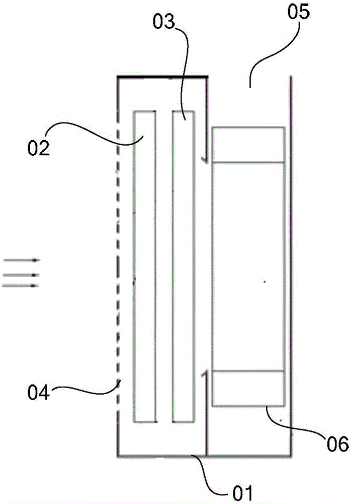
[0004] There are at least the following problems in the prior art: the existing household dehumidifier can condense the moisture in the air through the evaporator 02 to achieve the purpose of dehumidification, but it cannot remove the fine particles and dus

Method used


Image

  • Purification dehumidifier
  • Purification dehumidifier

Examples


Embodiment Construction

[0011] The following will clearly and completely describe the technical solutions in the embodiments of the present invention with reference to the accompanying drawings in the embodiments of the present invention. Obviously, the described embodiments are only some, not all, embodiments of the present invention. Based on the embodiments of the present invention, all other embodiments obtained by persons of ordinary skill in the art without making creative efforts belong to the protection scope of the present invention.

[0012] In describing the present invention, it is to be understood that the terms "center", "upper", "lower", "front", "rear", "left", "right", "vertical", "horizontal", The orientations or positional relationships indicated by "top", "bottom", "inner", "outer", etc. are based on the orientations or positional relationships shown in the drawings, and are only for the convenience of describing the present invention and simplifying the description, rather than indic


PUM


Abstract

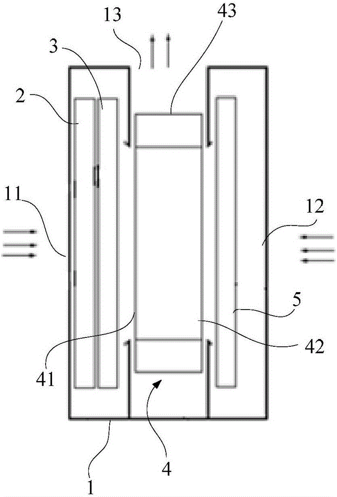
The invention discloses a purification dehumidifier and relates to the technical field of air conditioning. The purification dehumidifier aims at solving the problem that an existing dehumidifier does not have the air purification function and is low in usage rate. The purification dehumidifier comprises a shell, and an evaporator, a condenser and a draught fan are arranged in the shell. The evaporator and the condenser are connected into a refrigerant circulation pipeline. The shell is provided with a dehumidification air inlet and an air outlet. Air outside the shell can be pumped into the shell by the draught fan via the dehumidification air inlet, sequentially passes through the evaporator and the condenser, and then is exhausted from the air outlet. The shell is further provided with a purification air inlet, an air purification filter screen is arranged in the shell, and air outside the shell can be pumped into the shell by the draught fan via the purification air inlet, is filtered through the air purification filter screen and is exhausted from the air outlet. The purification dehumidifier can be used for humidity adjustment and purification of indoor air.

Description


Claims


Application Information

Patent Timeline
Owner HISENSE HOME APPLIANCES GRP CO LTD
Why Eureka
Try Eureka