External antenna device and its antenna structure

An antenna device and antenna structure technology, which is applied to antenna support/installation device, antenna grounding switch structure connection, and devices that enable antennas to work in different frequency bands at the same time, and can solve problems such as bandwidth limitation and impedance offset.

Pending Publication Date: 2017-04-26
YAODENG ELECTRONICS COMM TECH KUNSHAN CO LTD
View PDF4 Cites 2 Cited by
  • Summary
  • Abstract
  • Description
  • Claims
  • Application Information

AI Technical Summary

Benefits of technology

The inventors describe an improved design for electronic devices with wireless communication capabilities called Low Frequency (LF) technology. They use this new type of antennas instead of traditional types like spiral or monopole antennas because they can transmit signals at lower frequencies than regular wireline connections. This means more power will be used on these LF technologies compared to older methods such as radio waves.

Problems solved by technology

The technical problem addressed by this patented technology relates to improving the performance of external antennages used for wireless communication without limiting their operational range due to limited frequency bands being covered up during use.

Method used


Image

  • External antenna device and its antenna structure
  • External antenna device and its antenna structure
  • External antenna device and its antenna structure

Examples


Embodiment Construction

[0052] In order to make the above objects, features and advantages of the present invention more comprehensible, specific implementations of the present invention will be described in detail below in conjunction with the accompanying drawings.

[0053] see Figure 1 to Figure 9 , is an embodiment of the present invention. It should be explained first that this embodiment corresponds to the relevant quantities and shapes mentioned in the drawings, and is only used to specifically illustrate the implementation of the present invention, so as to facilitate the understanding of the content of the present invention. It is not intended to limit the protection scope of the present invention.

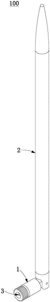
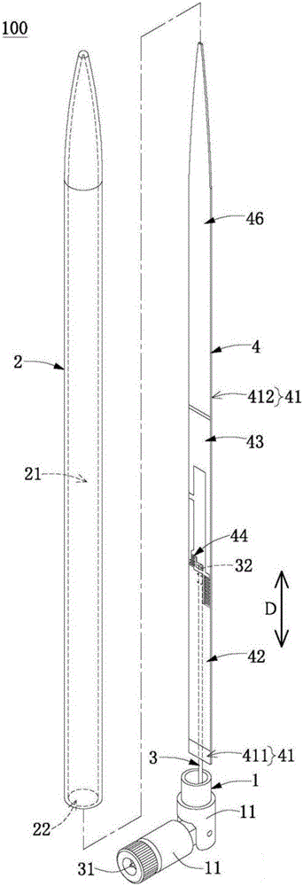
[0054] Such as figure 1 with figure 2 , the present embodiment discloses an external antenna device 100 for detachably installed on an electronic device (such as a sharer host). That is to say, the external antenna device 100 of this embodiment is different from the antenna (such as the mobil


PUM


Abstract

The present invention provides an external antenna device and an antenna structure thereof including an outer seat, an elongated case connected to an external seat, a signal cable formed in the outer socket and the housing, and an antenna structure disposed within the housing. The antenna structure comprises an elongated substrate and a ground section, an antenna section, a matching module, and a low frequency extension section provided on the substrate. The low-frequency extension section and the ground section are located on opposite sides of the antenna section. The antenna section includes a feeding part, a high frequency antenna part and a low frequency antenna part, and the signal cable is electrically connected with the grounding section and the feeding part. The high-frequency antenna section and the low-frequency antenna section are electrically connected to the feed section and the ground section via a matching module. The sum of the signal paths of the low frequency extension and the low frequency antenna sections is 0.375 times to 0.625 times the wavelength of the center frequency of the low frequency band to which it applies. The low frequency extension is spaced and electrically coupled to the antenna section.

Description


Claims


Application Information

Patent Timeline
Owner YAODENG ELECTRONICS COMM TECH KUNSHAN CO LTD
Why Eureka
Try Eureka