Linear generator test platform

A technology of linear generator and test platform, applied in the direction of motor generator test, measurement of electricity, measurement device, etc., can solve the problems of small test range, poor versatility, complex structure, etc., and achieves wide test range, convenient installation, and measurement accuracy. high effect

Active Publication Date: 2017-05-17
INST OF ELECTRICAL ENG CHINESE ACAD OF SCI
View PDF7 Cites 0 Cited by
  • Summary
  • Abstract
  • Description
  • Claims
  • Application Information

AI Technical Summary

Problems solved by technology

[0009] The purpose of the present invention is to overcome the shortcomings of the existing linear motor test device, such

Method used


Image

  • Linear generator test platform
  • Linear generator test platform
  • Linear generator test platform

Examples


Example Embodiment

[0032] The present invention will be further described below in conjunction with the drawings and specific embodiments.

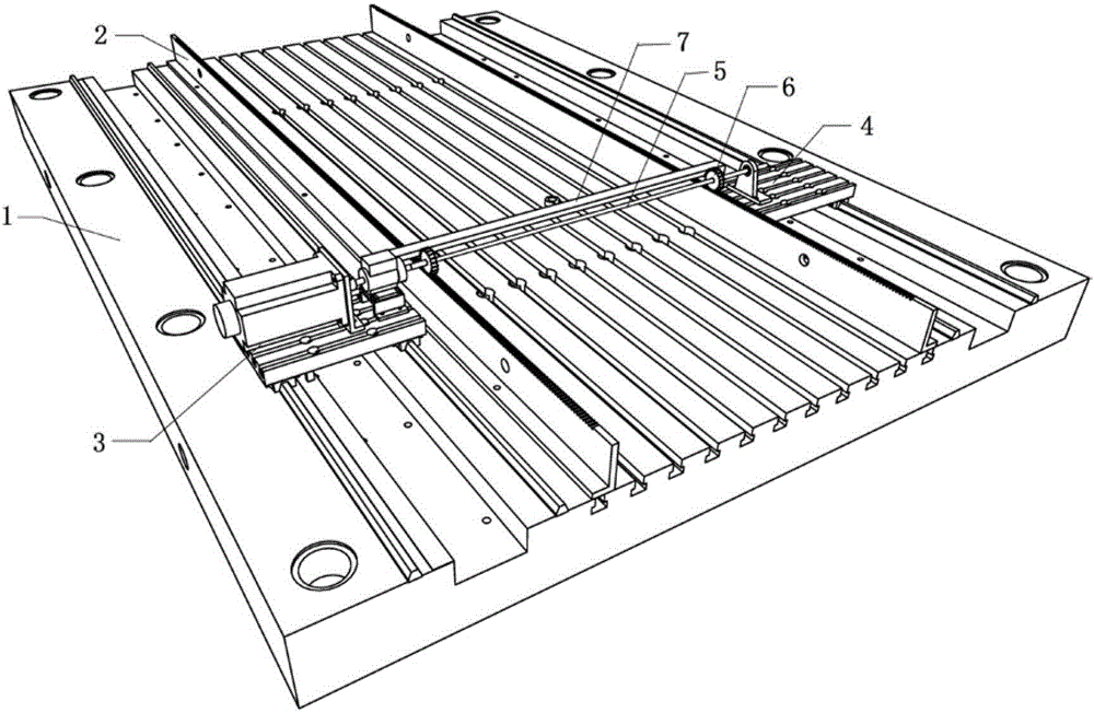
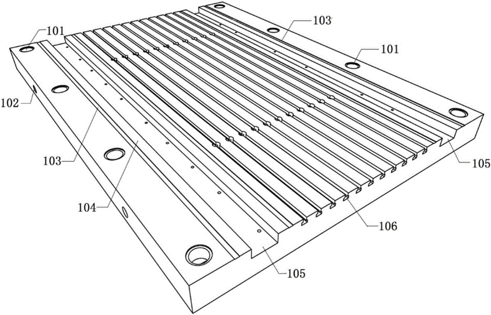
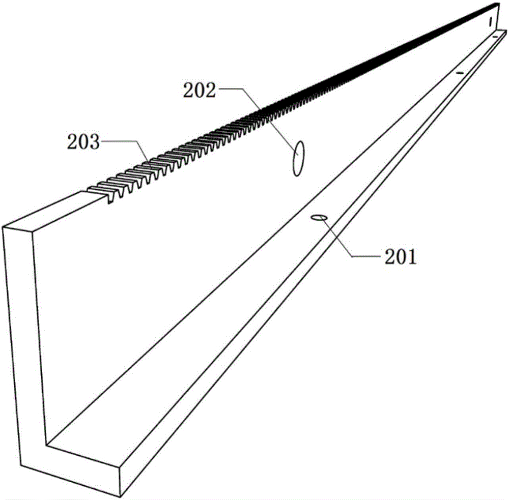
[0033] Such as figure 1 , figure 2 , Figure 4 with Figure 5 As shown, the linear generator test platform of the present invention includes a floor iron 1, a rack 2, a driving platform 3, a driven platform 4, a shaft 5, a gear 6, and a drag beam 7. The floor iron 1 is horizontally fixed to the ground through floor iron installation holes, two sets of guide rails 103 are installed on both sides of the floor iron 1 in parallel, and the floor iron 1 and the guide rail 103 are welded and fixed. The driving platform 3 and the driven platform 4 are respectively located on the guide rails 103 on both sides of the floor iron 1; the rack 2 is located between the driving platform 3 and the driven platform 4, and is fixed in parallel on the floor iron 1; Straddling between the driving table 3 and the driven table 4, the two ends of the shaft 5 are respectively connected w


PUM


Abstract

A linear generator test platform comprises a terrace iron (1), a tooth bar (2), a driving table (3), a driven table (4), a shaft lever (5), a gear (6) and a dragging beam (7). The terrace iron (1) is horizontally fixed at the ground, two sets of guide rails are installed in parallel at two sides of the terrace iron (1), and the terrace iron (1) are welded and fixed with the guide rails (103). The driving table (3) and the driven table (4) are respectively located at the guide rails (103) at the two sides of the terrace iron (1). The tooth bar (2) is located between the driving table (3) and the driven table (4) and fixed in parallel on the terrace iron (1). The shaft lever (5) crosses between the driving table (3) and the driven table (4), and the two ends of the shaft lever (5) are respectively connected with a torque sensor (305) and a bearing (405). The gear (6) passes through and fixed on the shaft lever (5), and is tightly fitted with the tooth bar (2). The dragging beam (7) crosses between the driving table (3) and the driven table (4), and the two ends of the dragging beam (7) are respectively connected with a driving terrace iron (301) and a driven terrace iron (401).

Description


Claims


Application Information

Patent Timeline
Owner INST OF ELECTRICAL ENG CHINESE ACAD OF SCI
Why Eureka
Try Eureka