Operating microscope and device for switching it between multiple operating modes

A technology of operating microscope and working mode, which is applied to the optical application solution of operating microscope, enables the operating microscope to switch between various working modes in the field of devices, which can solve the problems of high cost, error-prone, labor-intensive, etc. Ease of use, reduced size and weight, and the effect of saving interior space

Active Publication Date: 2019-03-15
CARL ZEISS MEDITEC AG
View PDF1 Cites 3 Cited by
  • Summary
  • Abstract
  • Description
  • Claims
  • Application Information

AI Technical Summary

Problems solved by technology

For the mode of manually moving the optical filters respectively, this makes the operation of manually moving the optical filters cumbersome, time-consuming, laborious and error-prone; for the mode of automatica

Method used


Image

  • Operating microscope and device for switching it between multiple operating modes
  • Operating microscope and device for switching it between multiple operating modes
  • Operating microscope and device for switching it between multiple operating modes

Examples


Example Embodiment

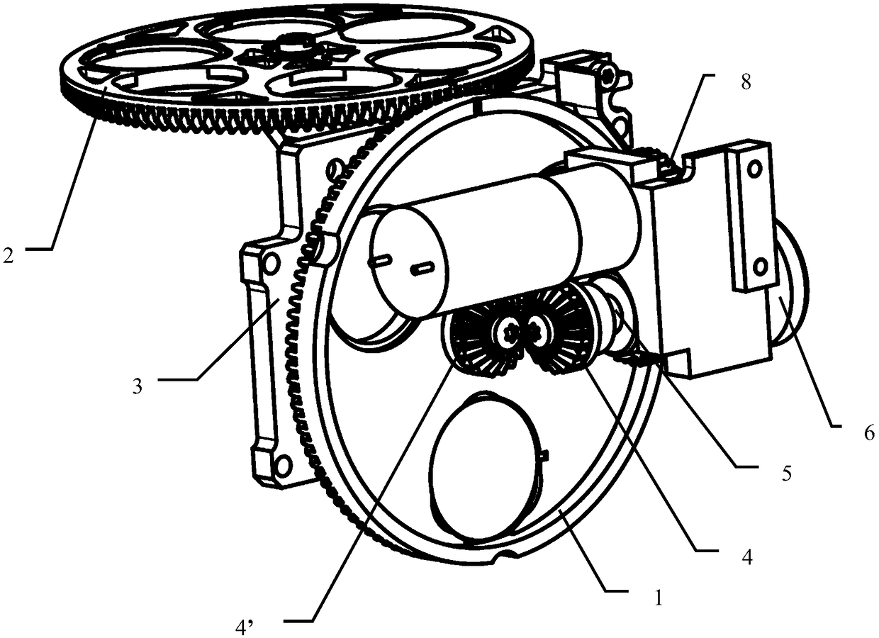
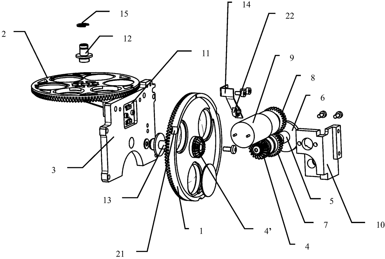
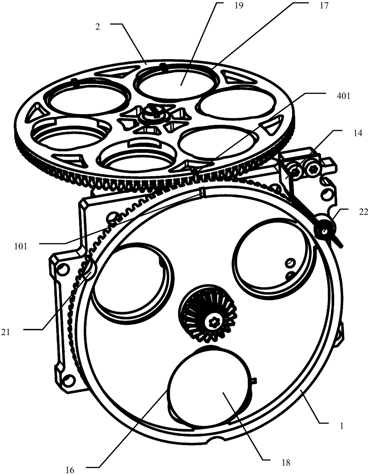
[0040] Hereinafter, referring to the drawings, an operating microscope according to an embodiment of the present invention and a device for switching between multiple operating modes will be described.

[0041] Such as Figure 1 to 3 As shown, the device for switching between multiple operating modes of an operating microscope according to an embodiment of the present invention mainly includes two rotating parts 1 and 2 respectively configured in the illumination light path and the observation light path of the operating microscope. Under the drive of the same power source, it rotates synchronously between a plurality of rotation positions corresponding to the plurality of working modes. In the present invention, the "rotation position" refers to the angular position of the rotation member 1 and / or 2 in the respective rotation direction (circumferential direction) due to rotation.

[0042] In the present invention, the illumination light path refers to the path that light passes thr


PUM

PropertyMeasurementUnit
Wavelengthaaaaaaaaaa
Center wavelengthaaaaaaaaaa

Abstract

The present invention relates to an operating microscope and a device for switching between multiple operating modes. The device includes an illumination rotating part respectively arranged in the illumination light path and the observation light path of the surgical microscope and capable of synchronously rotating between multiple rotation positions corresponding to the various working modes driven by the same power source and an observation rotating part, at each of said rotating positions, light from a light source of said surgical microscope passes through one or more of a plurality of light passing parts of said illuminating rotating part along said illuminating light path to irradiate to an observing On the object, one or more of the plurality of light passing parts along the observation optical path and passing through the observation rotating part arrive at the eyepiece of the surgical microscope.

Description


Claims


Application Information

Patent Timeline
Owner CARL ZEISS MEDITEC AG
Why Eureka
Try Eureka