Water block

Pending Publication Date: 2017-05-24
NORTHWESTERN POLYTECHN UNIV ZHANGJIAGANG INTELLIGENT EQUIP TECH INDZATION RES INST
View PDF4 Cites 0 Cited by
  • Summary
  • Abstract
  • Description
  • Claims
  • Application Information

AI Technical Summary

Benefits of technology

Problems solved by technology

This patented technical solution described by the inventors involves improving how well an electronic device's temperature control system works with liquid or gaseous fluids (liquid/gas). Water cools down parts like power supply chipsets but it does have its own limitations such as slow exchange rates due to dead angles between two ends caused by gravity effects. Conventional designs also reduce their strength because they require longer walls than necessary.

Method used


Image

  • Water block

Examples


Embodiment Construction

[0016] The present invention will be further described now in conjunction with accompanying drawing. These drawings are simplified schematic diagrams only to illustrate the basic structure of the present invention in a schematic way, so they only show the components relevant to the present invention.

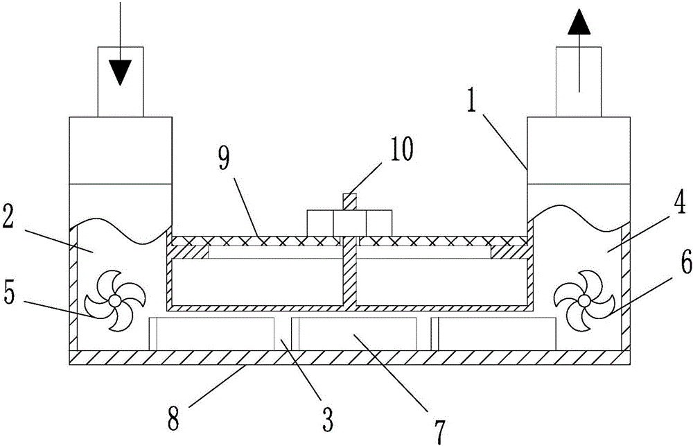
[0017] Such as figure 1 As shown, a water-cooled head includes a water-cooled housing 1 with a concave cross-section. A horizontally arranged heat dissipation chamber 3, a vertically arranged liquid inlet chamber 2, and a liquid outlet chamber 4 are formed in the water-cooled casing 1. The liquid inlet chamber 2 The upper end of the liquid inlet tube is provided with a round pipe, and the upper end of the liquid outlet chamber 4 is provided with a liquid outlet pipe.

[0018] The bottom plate of the water-cooled housing 1 is a heat dissipation bottom plate 8, and at least two sets of heat dissipation fins 7 are arranged on the heat dissipation bottom plate 8, preferably three sets


PUM


Abstract

The invention relates to a water block which comprises a water-cooled shell provided with a concave section. A horizontally arranged cooling cavity and a liquid inlet cavity and a liquid outlet cavity are formed in the water-cooled shell, the liquid inlet cavity and the liquid outlet cavity are vertically arranged, a round liquid inlet pipe is arranged in the upper end of the liquid inlet cavity, and a round liquid outlet pipe is arranged in the upper end of the liquid outlet cavity; a bottom plate of the water-cooled shell is of a cooling bottom plate, at least two sets of cooling fins are arranged on the cooling bottom plate, and the distance between upper ends of the cooling fins and the top wall of the cooling cavity is 1-3mm; a first water wheel is arranged at the bottom of the liquid inlet cavity, and a second water wheel is arranged at the bottom of the liquid outlet cavity. When waterflow flows among the liquid inlet cavity, the liquid outlet cavity and the cooling cavity, water flow at positions of dead space on two lower sides of the water-cooled body can be driven to flow by the aid of the water wheels in the water-cooled shell, and cooling capacity of the water block is improved.

Description


Claims


Application Information

Patent Timeline
Owner NORTHWESTERN POLYTECHN UNIV ZHANGJIAGANG INTELLIGENT EQUIP TECH INDZATION RES INST
Why Eureka
Try Eureka