Carbon emission management system radiography apparatus for cement enterprise

A management system and carbon emission technology, applied in the field of environmental management, can solve the problems of waste of resources, managers cannot intuitively see the difference in effect, etc., to achieve the effect of improving flexibility and simplicity, strong ease of use and practicability

Inactive Publication Date: 2017-05-31
东莞市维科应用统计研究所
View PDF0 Cites 0 Cited by
  • Summary
  • Abstract
  • Description
  • Claims
  • Application Information

AI Technical Summary

Benefits of technology

This patented technology helps gather data on how people emit greenhouse gases into our environment during different stages of production. It uses advanced numerical techniques that help create an image representation of these emissions from various sources such as factories, power plants, transportation vehicles, etc., allowing researchers to see what they are doing differently based upon its impacts. Overall this innovative solution makes it easier than previous ways to manage carbon-related issues more efficiently while also enhancing user friendliness and usableness across multiple industries.

Problems solved by technology

This patented describes two types of methods currently being developed: one involves limiting CO_emission levels produced during industrial activities while another focuses more specifically towards reducing environmental impacts associated with fossil fuel use. These techniques involve collective control over energy usage based upon factors like temperature and humidity level.

Method used


Image

  • Carbon emission management system radiography apparatus for cement enterprise
  • Carbon emission management system radiography apparatus for cement enterprise
  • Carbon emission management system radiography apparatus for cement enterprise

Examples


Embodiment Construction

[0045] In order to make the object, technical solution and advantages of the present invention clearer, the present invention will be further described in detail below in conjunction with the accompanying drawings.

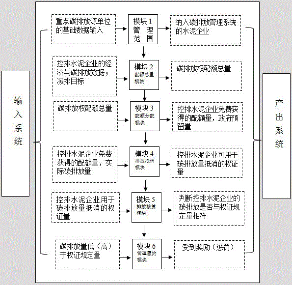
[0046] figure 1 It is the structural diagram of the imaging model of the carbon emission management system. The imaging model of the carbon emission management system includes a management scope module, a quota total module, a quota allocation module, a carbon emission accounting module, a carbon emission offset module, and a management compliance module.

[0047]Specifically, collect data, input the basic data of key carbon emission source units in the region into module 1, and obtain cement enterprises suitable for inclusion in the carbon emission management system through model calculations; collect economic and carbon emission data of emission-controlled cement enterprises, and set Determine the emission reduction target of the carbon emission management system,


PUM


Abstract

The invention is suitable for the technical field of environmental management and provides a carbon emission management system radiography apparatus for a cement enterprise. A method comprises data collection, system development and model building. According to the technical key points, the method comprises the steps of S1, extracting key public elements from domestic and overseas carbon emission management practices to form six core modules; S2, designing module contents; S3, performing module combination and connection according to logic functions of the modules; and S4, performing engineering radiography processing on the module functions to form a carbon emission management system radiography management model. A user can perform rehearsal on emission management process and result of greenhouse gases including methane, carbon dioxide, nitrous oxide and the like, so that the management efficiency can be greatly improved.

Description


Claims


Application Information

Patent Timeline
Owner 东莞市维科应用统计研究所
Why Eureka
Try Eureka