Multi-rotor-difference cascade permanent magnetic speed regulating device

A permanent magnet speed regulation and differential cascading technology, applied in electromechanical devices, permanent magnet clutches/brakes, electrical components, etc., can solve problems such as large axial pulling force, achieve high reliability, easy installation and debugging, simple structure

Pending Publication Date: 2017-05-31
DALIAN JIAOTONG UNIVERSITY
View PDF0 Cites 3 Cited by
  • Summary
  • Abstract
  • Description
  • Claims
  • Application Information

AI Technical Summary

Problems solved by technology

[0007] 2. Excessive axial pulling force when the existing air-gap flux adjustment mechanism adjusts speed

Method used


Image

  • Multi-rotor-difference cascade permanent magnetic speed regulating device
  • Multi-rotor-difference cascade permanent magnetic speed regulating device
  • Multi-rotor-difference cascade permanent magnetic speed regulating device

Examples


Example Embodiment

[0049] Example one:

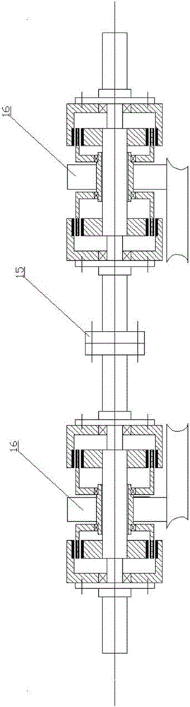
[0050] Such as Figure 1-3 As shown, the multi-slip cascade type permanent magnet speed control device includes a plurality of two-stage speed control modules 16, a plurality of two-stage speed control modules 16 are connected in series, and two adjacent two-stage speed control modules 16 pass between The coupling 15 is connected;

[0051] The two-stage speed control module 16 includes two symmetrically cascaded single-stage speed control modules, the structure of which is symmetrical about the left and right vertical center lines;

[0052] The single-stage speed regulation module includes an active rotor assembly, a speed regulation rotor assembly and a driven rotor assembly;

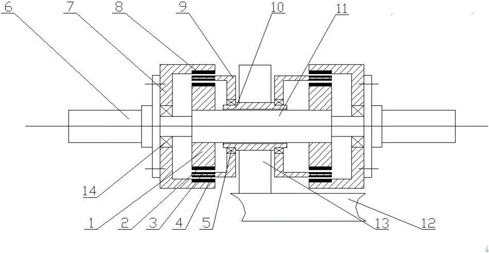
[0053] The active rotor assembly is composed of an end shaft 6, an outer sleeve 7, a good conductor B8 and a bearing B14; the end shaft 6 is a stepped shaft, and its largest diameter end is rigidly connected to the outer sleeve 7 by bolts or keys The outer sleeve 7 is a cylindrical structu

Example Embodiment

[0058] Embodiment two:

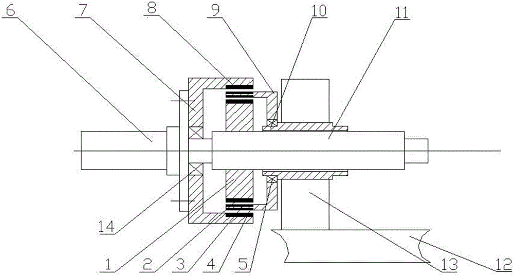
[0059] Such as figure 1 , 4 , 5, the multi-slip cascade permanent magnet speed control device includes a plurality of two-stage speed control modules 16, a plurality of two-stage speed control modules 16 are connected in series, and one of the two adjacent two-stage speed control modules 16 Are connected by coupling 15;

[0060] The two-stage speed control module 16 includes two symmetrically cascaded single-stage speed control modules, the structure of which is symmetrical about the left and right vertical center lines;

[0061] The single-stage speed regulation module includes an active rotor assembly, a speed regulation rotor assembly and a driven rotor assembly;

[0062] The active rotor assembly is composed of an end shaft 6, an outer sleeve 7, a permanent magnet B4 and a bearing B14; the end shaft 6 is a stepped shaft, and its largest diameter end is rigidly connected to the outer sleeve 7 by bolts or keys The outer sleeve 7 is a cylindrical structure, it

Example Embodiment

[0067] Embodiment three:

[0068] Such as figure 2 , 4 As shown, the multi-slip cascade permanent magnet speed control device includes a two-stage speed control module 16 with the left end shaft 6 as the input shaft and the right end shaft 6 as the output shaft.


PUM


Abstract

The invention discloses a multi-rotor-difference cascade permanent magnetic speed regulating device, which comprises a plurality of double-stage speed regulating modules, wherein the plurality of double-stage speed regulating modules are connected in series; the two adjacent double-stage speed regulating modules are connected through a shaft coupler; each double-stage speed regulating module comprises two symmetrical cascade single-stage speed regulating modules including a left cascade single-stage speed regulating module and a right cascade single-stage speed regulating module; each single-stage speed regulating module comprises an active rotor assembly, a speed regulating rotor assembly and a driven rotor assembly. The big rotor difference required during the speed regulation of the permanent magnetic speed regulating device can be decomposed into the small rotor difference with multilayer air gaps; the heat generating quantity of the permanent magnetic speed regulating device in the small rotor difference state is very small, so that the integral heating quantity is small even when the rotor difference required by the input end and the output end of the permanent magnetic speed regulating device is great. The multi-rotor-difference cascade permanent magnetic speed regulating device has the advantages that an axial air gap magnetic flux regulating mechanism is provided with no spline pair; during the speed regulation, the axial air gap magnetic flux regulating mechanism only needs to overcome the axial component of the air gap magnetic field tension force, so that the size of the axial air gap magnetic flux regulating mechanism is small; the structure is simple; the work performance is good; the reliability is high.

Description


Claims


Application Information

Patent Timeline
Owner DALIAN JIAOTONG UNIVERSITY
Why Eureka
Try Eureka