Multifunctional heat pump system

A heat pump system and multi-functional technology, applied in heat pumps, lighting and heating equipment, damage protection, etc., can solve problems such as frequent start-up of compressors, unstable working conditions of heat pump units, overheating of compressor motors, etc., and achieve hot gas bypass Mixed energy adjustment, realize hot gas bypass energy adjustment function, and avoid the waste of equipment

Pending Publication Date: 2019-01-15
TIANJIN UNIV OF COMMERCE
View PDF0 Cites 0 Cited by
  • Summary
  • Abstract
  • Description
  • Claims
  • Application Information

AI Technical Summary

Problems solved by technology

Judging from the actual operation effect of the current small air source heat pumps, the unit is still not ideal for heating. When the cooling load is low or the outdoor ambient temperature is low, the suction pressure of the compressor is low, and the flow rate of the circulating refrigerant is small, which will cause insufficient oil return of the compressor lubricating oil, resulting in deterioration of the lubrication conditions and wear of the compressor cylinder
Moreover, long-term operation of the system below the designed suction pressure will cause the compressor motor to overheat, resulting in damage to the compressor motor coil
In order to protect the compressor, a low-pressure shutdown fault is usually added to the control system, that is, the compressor will stop immediately when the suction pressure is too low, and the compressor will not be allowed to start until the suction pressure rises to a safe value. The compressor starts frequently, which shortens the life of the compressor
Secondly, the most common defrosting method for air source heat pump units is reverse cycle defrosting. This defrosting method has many disadvantages. For example, it needs to absorb heat from the room during defrosting, and the room temperature will drop by 5-6°C, which will affect the comfort of the room. ;When switching between heating and defrosting modes, the system pressure fluctuates violently, resulting in a relatively large mechanical impact; when defrosting, the indoor heat exchanger is used as an indoor heat exchanger, and the surface temperature is as low as -20~-25°C. After that, no hot air can be blown out for a long period of time; when the defrosting is started and terminated, the four-way valve reversing produces a large airflow noise, and this defrosting method will reduce the indoor temperature during defrosting, and the noise is relatively large
Thirdly, considering the cost, the capacity of the indoor and outdoor heat exchangers of the existing small heat pump units is fixed, and the working conditions of the heat pump units are unstable all the year round. When the unit is supplying cooling and heat, the capacity of the indoor and outdoor heat exchangers cannot Condition change regulation
In addition, for the application of heat pump units in multiple rooms such as homes and hotels, a small heat pump unit is mostly used in each room. Each heat pump unit is completely independent and has no connection. However, the cooling or heating requirements of each room are different. , when the small heat pump unit is not working, the waste of equipment is formed, and all the devices in the small heat pump system are single, and the damage of one device will lead to the paralysis of the entire heat pump system. Considering the cost saving, generally do not design spare devices, Affect the normal operation of the entire system

Method used


Image

  • Multifunctional heat pump system
  • Multifunctional heat pump system

Examples


Example Embodiment

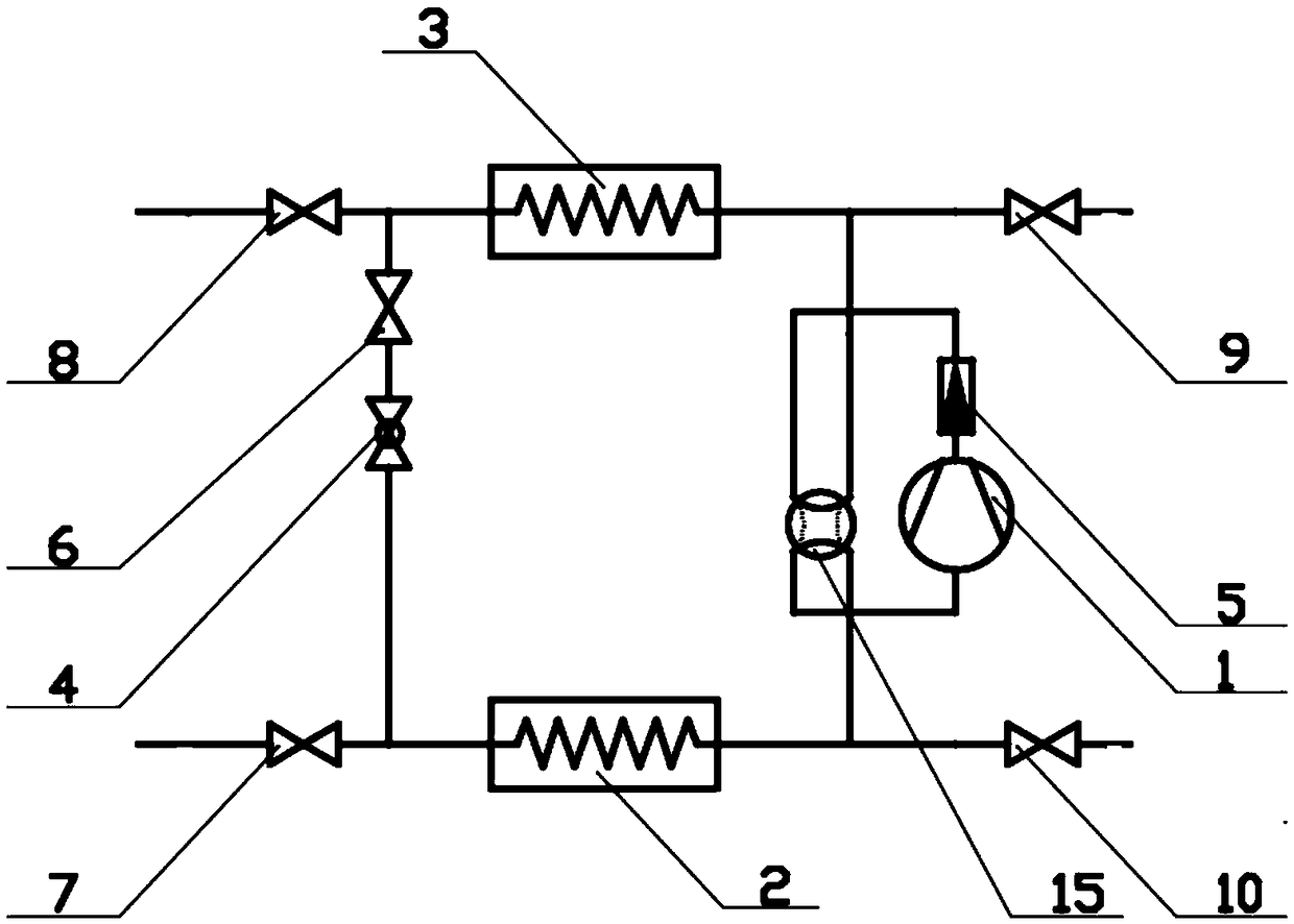
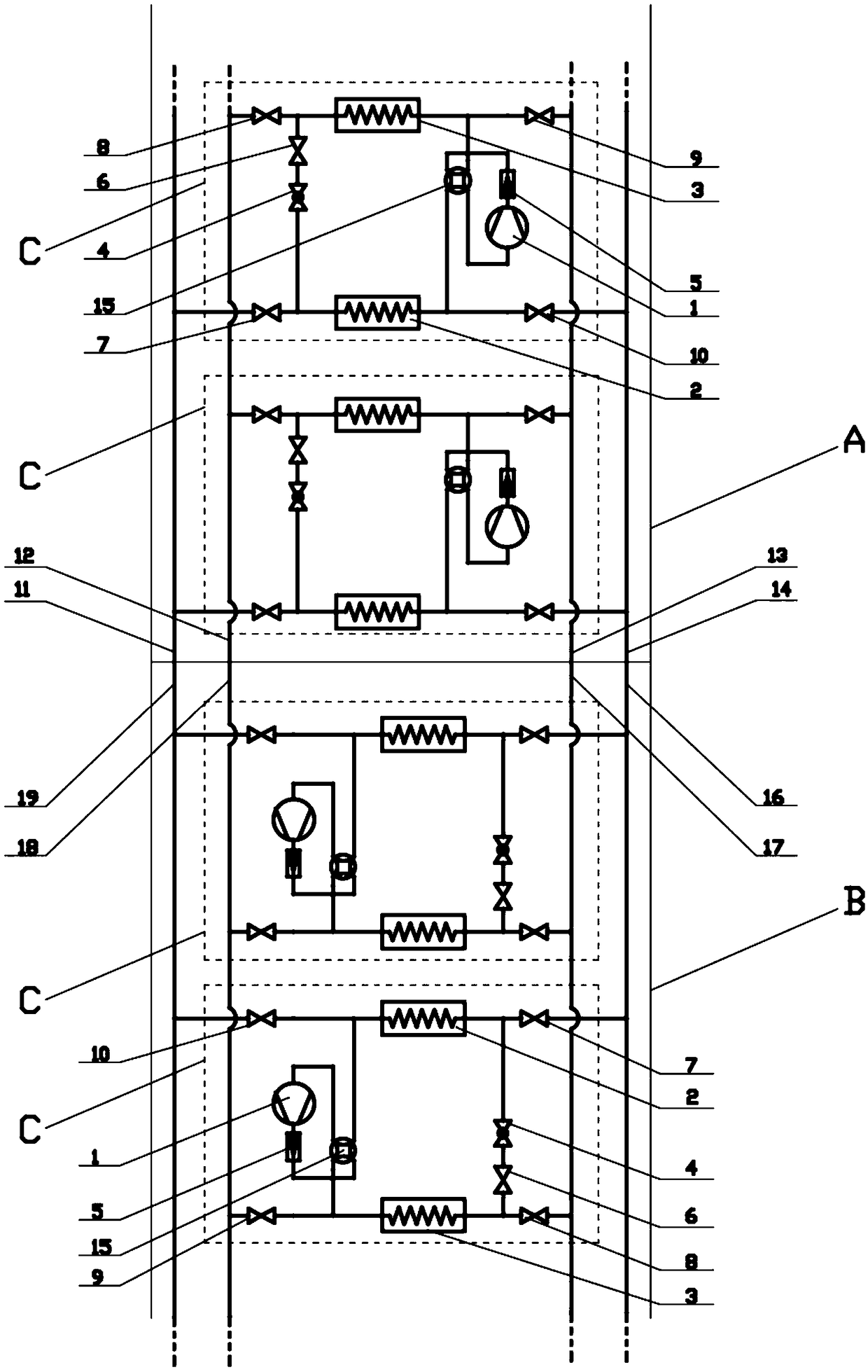
[0029] Embodiment 1: Take the heat pump module in the second heat pump unit B for the cooling process, the heat pump module in the first heat pump unit A performs the bypass adjustment process as an example, that is, in the second heat pump unit B as the cooling process The refrigeration compressor in the heat pump module is running, and the refrigeration compressor in the heat pump module A in the first heat pump unit A of the bypass adjustment process is stopped. The bypass adjustment process includes: (1), hot air bypass to the energy-regulated thermodynamic cycle at the suction end of the refrigeration compressor; (2) hot air bypass to the energy-regulated thermodynamic cycle at the entrance of the indoor heat exchanger; (3), hot air bypass The energy mixed at the suction end of the compressor and the inlet of the indoor heat exchanger adjusts the thermodynamic cycle. The first valve 7, the second valve 8, the third valve 9 and the fourth valve 10 in the heat pump modules in t

Example Embodiment

[0035] Embodiment 2: Take the second heat pump unit B for the heating process, the first heat pump unit A for the bypass adjustment process or the outdoor heat exchanger defrosting process as an example, that is, the second heat pump unit as the heating process The refrigeration compressor in the heat pump module in B operates, and the refrigeration compressor in the heat pump module in the heat pump module A in the first heat pump unit A is stopped as a bypass adjustment process or an outdoor heat exchanger defrosting process. The bypass and defrost process are: (1) hot gas bypass to the energy-regulated thermodynamic cycle at the suction end of the refrigeration compressor; (2) hot gas bypass to the energy-regulated thermodynamic cycle at the entrance of the outdoor heat exchanger; (3) hot gas bypass The energy mix at the suction end of the compressor and the entrance of the outdoor heat exchanger to adjust the thermodynamic cycle; (4) Defrost cycle of the outdoor heat exchanger.


PUM


Abstract

The invention discloses a multifunctional heat pump system, and aims to provide a heat pump system which is suitable for a small heat pump system and can be implemented by splicing a plurality of heatpump modules. The multifunctional heat pump system comprises a first heat pump unit and a second heat pump unit, wherein each of the first heat pump unit and the second heat pump unit comprise a plurality of heat pump modules of the same structure; and each heat pump module comprises a refrigeration compressor, an outdoor heat exchanger, an indoor heat exchanger, a four-way reversing valve, an expansion valve, a one-way valve, a first valve, a second valve, a third valve, a fourth valve and a fifth valve. The multifunctional heat pump system can realize hot-gas bypass circulation in various forms during the summer cooling and winter heating, can realize the effect of defrosting the indoor heat exchanger by means of hot-gas bypass in winter heating, and has simple structure and high energyefficiency ratio.

Description


Claims


Application Information

Patent Timeline
Owner TIANJIN UNIV OF COMMERCE
Why Eureka
Try Eureka