Bone ash storing chamber cemetery in mountain body

A technology for chambers and ashes, applied in tombs, building types, buildings, etc., can solve the problems of reducing funeral costs and the occupation of funeral facilities, and achieve the effect of meeting individual requirements, reducing cost investment, and reducing financial pressure.

Pending Publication Date: 2017-10-20
周惠君 +1
View PDF8 Cites 0 Cited by
  • Summary
  • Abstract
  • Description
  • Claims
  • Application Information

AI Technical Summary

Problems solved by technology

[0006] Aiming at the deficiencies of the prior art, the present invention provides a cemetery in a cave where ashes are placed

Method used


Image

  • Bone ash storing chamber cemetery in mountain body
  • Bone ash storing chamber cemetery in mountain body
  • Bone ash storing chamber cemetery in mountain body

Examples


Embodiment 1

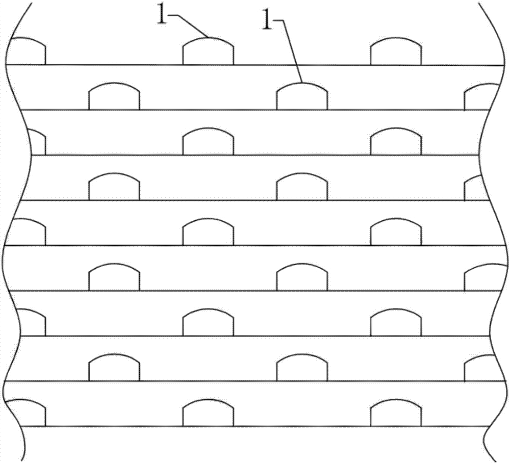
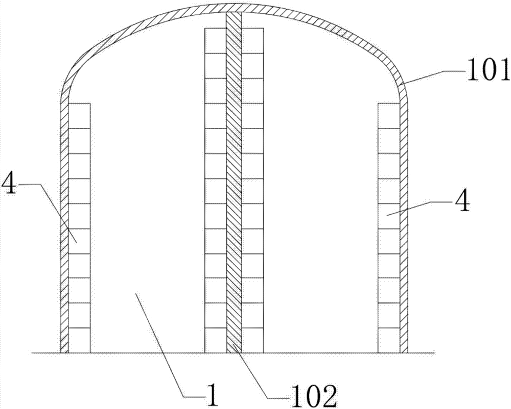
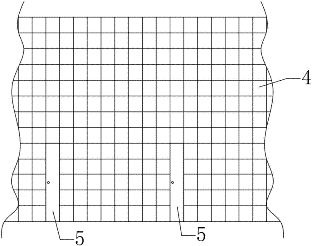
[0050] The columbarium burial chamber cemetery in this embodiment includes multiple chamber layers according to different heights, and each chamber layer includes a plurality of mutually parallel columbarium burial chambers 1 set in the mountain body. 1. The sidewalk 2 arranged on the outside of the mountain and the connecting road 3 arranged inside the mountain, the entrance and tail ends of the multiple ashes storage chambers 1 are respectively connected with the sidewalk 2 and the connecting road 3; the ashes storage chamber 1 A plurality of ashes storage units 4 are arranged inside; the centerlines of the ashes storage chambers 1 of the upper and lower adjacent two-story chambers are arranged to be staggered from each other (see figure 1 , Figure 6 , Figure 11 and Figure 12 ).

[0051] Wherein, the side walls and tops of the ashes storage chamber 1 and the connecting road 3 are respectively sprayed with a concrete mortar layer 101 and a concrete mortar layer 301 .

[0


PUM

PropertyMeasurementUnit
Thicknessaaaaaaaaaa
Thicknessaaaaaaaaaa
Heightaaaaaaaaaa

Abstract

The invention relates to a bone ash storing chamber cemetery in a mountain body. The chamber cemetery comprises N chamber layers. The N chamber layers comprise one or more bone ash storing chambers formed in the mountain body and sidewalks arranged on the periphery of the mountain body, and the inlet ends of the bone ash storing chambers communicate with the sidewalks. The bone ash storing chambers are internally provided with a plurality of bone ash storing units, when N is equal to or larger than 2, the bone ash storing chambers of every two vertically-adjacent chamber layers are mutually arranged in a staggered mode, and N is a positive integer. According to the bone ash storing chamber cemetery in the mountain body, the mountain body is completely utilized for building the chamber cemetery, the land for normal living, production and work of humans is not occupied, and the problem of land storage can be solved or relieved to a great extent. The arranged quantity of the bone ash storing units in the single bone ash storing chamber can be large, the engineering manufacturing cost is few, the cost input is greatly reduced, the input and output ratio is up to 6-10, and the financial pressure of common people for buying coffin pits is greatly reduced.

Description


Claims


Application Information

Patent Timeline
Owner 周惠君
Why Eureka
Try Eureka