Speed limit circuit for electric bicycle

A technology of electric bicycles and circuits, which is applied in the direction of circuit devices, emergency protection circuit devices, automatic disconnection emergency protection devices, etc., can solve the problems of increasing the cost of electric bicycles, inconvenient popularization and use, and high production costs, and achieves good application prospects , simple circuit, simple control effect

Inactive Publication Date: 2017-11-10
SUZHOU CRABCHINA E COMMERCE CO LTD
View PDF0 Cites 0 Cited by
  • Summary
  • Abstract
  • Description
  • Claims
  • Application Information

AI Technical Summary

Problems solved by technology

[0003] The purpose of the present invention is to overcome the speed-limiting circuit of the electric bicycle on the market, the circuit is complic

Method used


Image

  • Speed limit circuit for electric bicycle

Examples


Embodiment Construction

[0013] The present invention will be further described below in conjunction with the accompanying drawings. The following examples are only used to illustrate the technical solution of the present invention more clearly, but not to limit the protection scope of the present invention.

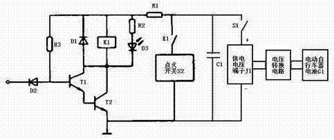
[0014] Such as figure 1 As shown, the speed limiting circuit for electric bicycles of the present invention includes a power supply voltage terminal J1, the positive pole of the power supply voltage terminal J1 is connected in series with a switch S1, and the switch S1 is respectively connected to one end of the resistance R2 and the relay K1 through the resistance R1. One end of the coil, the cathode of the diode D1, and one end of the resistor R3 are connected, the other end of the resistor R3 is connected to the base of the transistor T1, the base of the transistor T1 is connected to the anode of the diode D2, and the base of the diode D2 The negative pole is connected to the speedometer of the


PUM


Abstract

The invention discloses a speed limiting circuit for an electric bicycle. The base of the transistor T1 is connected to the anode of the diode D2, the cathode of the diode D2 is connected to the speedometer of the electric bicycle, and the emitter of the transistor T1 is connected to the base of the transistor T2. Connection, the collector of transistor T1 is connected with the anode of diode D1 and the other end of relay K1 coil respectively, the collector of transistor T2 is connected with the other end of relay K1 coil, the collector of transistor T2 is also connected with the negative pole of light-emitting diode D3 The positive pole of the light-emitting diode D3 is connected to the other end of the resistor R2, one end of the normally closed contact switch of the relay K1 is connected to the positive pole of the supply voltage terminal J1, and the other end of the normally closed contact switch of the relay K1 passes through the ignition switch S2 Connect to the negative pole of the supply voltage terminal J1. The invention has simple control, simple circuit, easy realization and good application prospect.

Description


Claims


Application Information

Patent Timeline
Owner SUZHOU CRABCHINA E COMMERCE CO LTD
Why Eureka
Try Eureka