Cooling device in natural gas liquefaction technology
A cooling device, natural gas technology, applied in liquefaction, refrigeration and liquefaction, cold treatment separation, etc., can solve the problems of guaranteed cooling effect, waste of energy consumption, difficulty in ensuring uniform contact of air coolers, etc., and achieve increased cooling efficiency and improved cooling effect , the effect of reducing the energy consumption state
- Summary
- Abstract
- Description
- Claims
- Application Information
AI Technical Summary
Benefits of technology
Problems solved by technology
Method used
Image

Examples
Embodiment 1
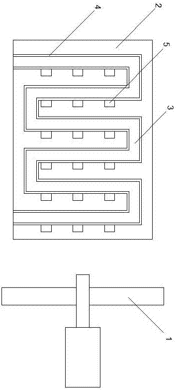
[0015] Such as figure 1 Shown is a cooling device in a natural gas liquefaction process, the cooling device in the natural gas liquefaction process includes an air cooler 1, and a radiator 2 opposite to the air cooler 1, and a radiator 2 is arranged on the radiator 2 pipeline 3; in the radiator 2, auxiliary cooling tanks 4 are respectively arranged on both sides of the heat dissipation pipeline 3, which extend parallel to the heat dissipation pipeline 3; a plurality of micro air pumps 5 are arranged in the radiator 2, A plurality of micro air pumps 5 are evenly distributed along the auxiliary cooling tank body 4 .
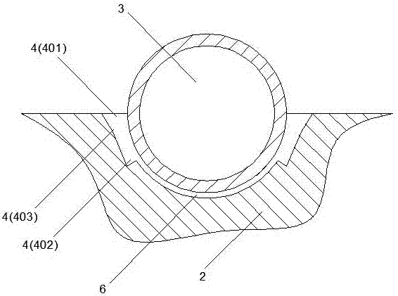
[0016] As an improvement of the present invention, such as figure 2 As shown, in the radiator 2 , each auxiliary cooling tank 4 extends obliquely from the end surface of the radiator 2 toward the bottom end of the heat dissipation pipe 3 in its width direction. By adopting the above technical solution, the extension direction of the auxiliary cooling tank can be se
Embodiment 2
[0019] As an improvement of the present invention, in the radiator 2, a plurality of connected connecting pipes 6 are arranged between the auxiliary cooling tanks 4 located on both sides of the heat dissipation pipe 3 respectively. By adopting the above technical solution, the two auxiliary cooling tanks can be connected through the arrangement of the connecting pipes, thereby improving the passing efficiency of the internal airflow, so that the cooling efficiency can also be increased accordingly.
[0020] The remaining features and advantages of this embodiment are the same as those of Embodiment 1.
Embodiment 3
[0022] As an improvement of the present invention, each auxiliary cooling tank body 4 includes a first end portion 401 extending above the end surface of the radiator 2 and a second end portion 402 extending into the inside of the radiator, the auxiliary cooling tank body A third end portion 403 is provided between the first end portion 401 and the second end portion 402, the width of the auxiliary cooling tank 4 gradually decreases through the first end portion 401 toward the third end portion 403, and from the third end portion 403 gradually increases towards the second end 402 . With the above technical solution, the width of the auxiliary cooling tank can be set gradually so that the corresponding position of the second end of the auxiliary cooling tank can form a negative pressure effect relative to the corresponding position of the first end, so that the bottom of the auxiliary cooling tank can be The adsorption effect is formed on the cooling air flow, so that the cooling
PUM
 Abstract
Description
Claims
Application Information
 - R&D Engineer
- R&D Manager
- IP Professional
- Industry Leading Data Capabilities
- Powerful AI technology
- Patent DNA Extraction
Browse by: Latest US Patents, China's latest patents, Technical Efficacy Thesaurus, Application Domain, Technology Topic.
© 2024 PatSnap. All rights reserved.Legal|Privacy policy|Modern Slavery Act Transparency Statement|Sitemap