Detection method, device and system
A detection method and detection device technology, applied in the fields of detection methods, devices and systems, can solve the problems of increasing the work complexity of operation and maintenance personnel, affecting the operation of the monitoring system, and reducing the efficiency of troubleshooting, so as to improve the efficiency of troubleshooting and avoid data Acquisition and processing, the effect of reducing operational complexity
- Summary
- Abstract
- Description
- Claims
- Application Information
AI Technical Summary
Benefits of technology
Problems solved by technology
Method used
Image

Examples
Embodiment 1
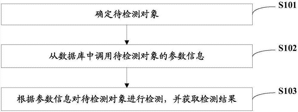
[0049] This embodiment provides a detection method, please refer to figure 1 , the specific detection steps are as follows:
[0050] S101, determining an object to be detected;
[0051] Specifically, the objects to be detected include basic equipment, such as refrigeration equipment, power distribution equipment, temperature and humidity, water leakage detection and other sensor equipment. Through the monitoring data of these basic equipment, key data such as the operating status and energy consumption of the data center can be checked in a timely and accurate manner. .
[0052] S102, call the parameter information of the object to be detected from the database;
[0053] Specifically, a large amount of parameter information of basic equipment is collected in the database, such as equipment information and a list of corresponding parameters. The equipment information includes the protocol type, IP address, port, etc. of the equipment. When detecting the object to be detected, t
Embodiment 2
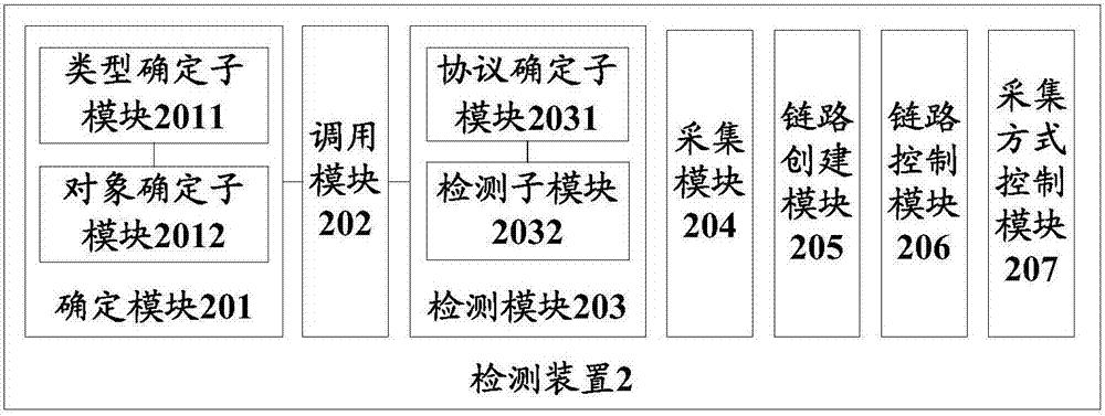
[0067] The detection method in the first embodiment above can be applied to the detection device provided in this embodiment, so this embodiment does not describe some modules in the detection device in detail. For details, please refer to the relevant description in the first embodiment. For details, please refer to figure 2 , figure 2 The schematic structural diagram of the detection device provided in this embodiment, the specific structure of the device is as follows:
[0068] A determining module 201, configured to determine an object to be detected;
[0069] Calling module 202, for calling the parameter information of the object to be detected from the database;
[0070] The detection module 203 is configured to detect the object to be detected according to the parameter information, and obtain a detection result.
[0071] The above objects to be detected include basic equipment, such as refrigeration equipment, power distribution equipment, temperature and humidity, w
Embodiment 3
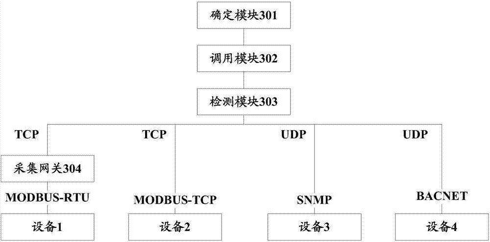
[0079] This embodiment is based on the detection device provided in the second embodiment above, and describes the functions realized by the detection device. Specifically, link detection will be used as an example to explain the present invention. For details, please refer to Figure 4 , Figure 4 The link detection flow chart provided for this embodiment, the specific detection process is as follows:
[0080] S401, determining that the module selects a link detection function;
[0081] Specifically, the link detection function is selected by the determination module, and the functions that the system can perform include but are not limited to link detection, parameter detection, parameter collection mode control, and link control. This embodiment uses the link detection function as an example for illustration.
[0082] S402, the determining module selects a device that requires link detection and sends a request to the calling module;
[0083] S403, the calling module calls t
PUM
 Abstract
Description
Claims
Application Information
 - R&D Engineer
- R&D Manager
- IP Professional
- Industry Leading Data Capabilities
- Powerful AI technology
- Patent DNA Extraction
Browse by: Latest US Patents, China's latest patents, Technical Efficacy Thesaurus, Application Domain, Technology Topic.
© 2024 PatSnap. All rights reserved.Legal|Privacy policy|Modern Slavery Act Transparency Statement|Sitemap