Walking beam type pumping unit working system combined operation method

A technology of beam pumping unit and working system, which is applied in the direction of earthwork drilling, production fluid, wellbore/well components, etc., which can solve the problems of low motor drive efficiency, high plunger leakage rate, single well production and oil-producing layer development Unfavorable effects and other problems, to meet the needs of safety warnings, solve the high leakage rate of the plunger, and eliminate the need for start-up operation

Active Publication Date: 2017-11-24
张敏 +3
View PDF8 Cites 5 Cited by
  • Summary
  • Abstract
  • Description
  • Claims
  • Application Information

AI Technical Summary

Benefits of technology

This patented technology allows us to allocate more space on one side compared with another without reducing their performance or causing issues like excessive pressure during use. It uses specific numbers that are allocated based upon certain cycles within an overall period called its operating range (OCR). These speeds help prevent leaks from happening overall while maintaining high power output by utilizing less energy than usual. Additionally, it suggests dividing up work between two periods instead of just once every other day when doing regular strokes at different points along the entire process. Overall, these technical improvements improve fuel economy and decrease costs associated therewith.

Problems solved by technology

Technological Problem addressed in this patents relates to improving the performance of a beam pumpsing unit (BP) during certain operations such as filling crude oil into subterranean formations while avoiding excessive power usage and maintaining stable operation over longer periods. Current methods involve changing gears between different modes, leading to slowdown and unstable movements. Additionally, current solutions require multiple steps before moving parts towards each other again after turning off one piece of equipment.

Method used


Image

  • Walking beam type pumping unit working system combined operation method
  • Walking beam type pumping unit working system combined operation method
  • Walking beam type pumping unit working system combined operation method

Examples


specific Embodiment 1

[0027] The combined operation method of the working system of the beam pumping unit in this embodiment,

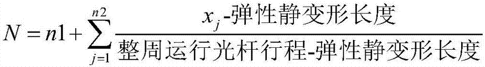
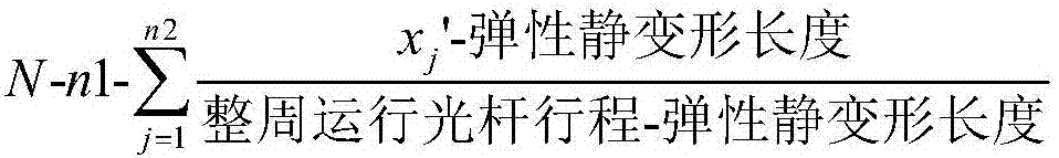
[0028] According to the theoretical round number N in the period T, the following conditions are met:

[0029]

[0030]

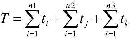
[0031] Assign the number of times n1 of the crank to run in a full cycle, and the time t for each full cycle 1 , t 2 ,...,t n1 ;The number of pumping operations n2 of the crank part-cycle, and the stroke of the polished rod x in each part-cycle part of the pumping operation 1 、x 2 ,...,x n2 , each part-week has a swabbing run time t 1 , t 2 ,...,t n2 ;Crank non-full cycle without swabbing operation times n3, each partial cycle with swabbing time t 1 , t 2 ,...,t n3 ; and the sequence of the crank full circle running, the crank part full circle with swabbing operation, and the crank part part full circle without swabbing.

[0032] This embodiment also has the following three points to be explained:

[0033] First, the concept of cycle in t

specific Embodiment 2

[0036] The working system combination operation method of the beam pumping unit in this embodiment, on the basis of the specific embodiment 1, further limits that the duration of the non-full cycle of the crank without swabbing does not exceed the threshold value of the sedimentation time, the threshold value of the waxing time, the freezing time The minimum value of the blocking time threshold and stratification time threshold.

[0037] If there is no pumping for a long time during operation, problems of sand settling, wax formation, freezing blockage, or stratification will occur. However, this technical solution limitation can effectively avoid the problems of sand settling, wax formation, freezing blockage, and stratification when the non-swabbing operation time is too long.

specific Embodiment 3

[0038] The working system combination operation method of the beam pumping unit in this embodiment, on the basis of the specific embodiment 1, further limits the duration of the non-full circle non-swabbing operation with a crank angle of less than 90 degrees to not exceed the requirements of the reducer gearbox Lubrication time threshold.

[0039] Since the gears in the gear box of the beam pumping unit reducer are arranged horizontally, if the crank swings at a rotation angle of less than 90 degrees during operation, there is a problem that the lubricating oil cannot lubricate the contact surfaces of the two gears. Swinging like this for a long time will affect the service life of the reducer gearbox. And this technical scheme is limited, can guarantee that gear is fully lubricated, prolongs the service life of gear box of pumping unit reducer.


PUM


Abstract

The invention provides a walking beam type pumping unit working system combined operation method and belongs to the field of oil production engineering. According to the theoretical whole pumping number in a cycle, the crank whole-cycle operation frequency, the used time of operation of each whole cycle, the crank non-whole-cycle swabbing operation frequency, the swabbing operation polished rod stroke of each non-whole cycle, the used time of swabbing operation of each non-whole cycle, the crank non-whole-cycle swabbing-free operation frequency, the used time of swabbing operation of each non-whole cycle and the sequence of crank whole-cycle operation, crank non-whole-cycle swabbing operation and crank non-whole-cycle swabbing-free operation are distributed. According to walking beam type pumping unit working system combined operation method, the whole-cycle jig frequency does not need to be decreased, solving of the problems that the leak rate of a plunger is large and the driving efficiency of a motor is low is facilitated, the requirement of starting up for operation is avoided, and consumption, of the manpower, materials and financial resources, caused by the fact that people go to a construction site to conduct starting-up for operation is reduced disadvantageously; and meanwhile the safe warning requirement can further be met, a crank is made to swing obviously, and the swabbing movement requirement for sand jamming, wax deposit, frozen blocking and laying problems is taken into consideration.

Description


Claims


Application Information

Patent Timeline
Owner 张敏
Why Eureka
Try Eureka