Instrument transformer

A technology of transformer and shell, applied in the field of transformers, can solve the problems of poor heat dissipation effect, etc., and achieve the effect of easy installation and disassembly, guaranteeing internal circuits, and convenient installation.

Inactive Publication Date: 2017-11-24
YANTAI POWER SUPPLY COMPANY OF STATE GRID SHANDONG ELECTRIC POWER +1
View PDF8 Cites 0 Cited by
  • Summary
  • Abstract
  • Description
  • Claims
  • Application Information

AI Technical Summary

Problems solved by technology

[0003] The wiring part of the transformer is usually used to access external current or voltage. The wiring piece usually includes a connecting part b and a connecting part a. In the prior art, the connecting part b and the two connecting parts a are

Method used


Image

  • Instrument transformer
  • Instrument transformer
  • Instrument transformer

Examples


Embodiment Construction

[0025] The following will clearly and completely describe the technical solutions in the embodiments of the present invention with reference to the drawings in the embodiments of the present invention.

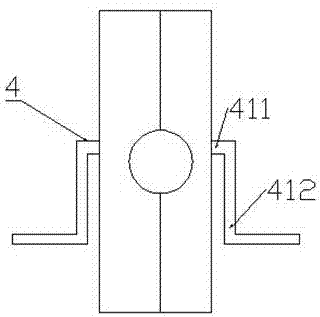
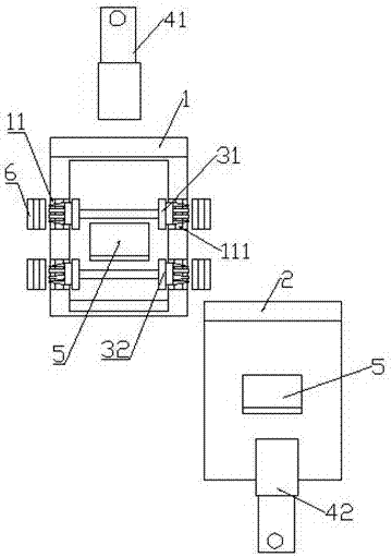
[0026] Such as Figure 1-6 As shown, it is a transformer of the present invention, including a first casing 1, a second casing 2, a coil, and a wiring device 4; the first casing 1 and the second casing 2 are detachably connected to form a transformer Shell; the coil is arranged in the shell composed of the first shell 1 and the second shell 2, and the shell is provided with a rectangular opening 5 for installing the wiring device 4;

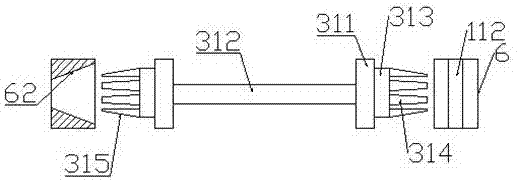
[0027] The coil includes coil a31 arranged in the upper cavity of the shell and coil b32 arranged in the lower cavity of the shell; The winding body 312; the outer side of the fixed gear ring 311 is provided with a connector for fixing the coil a31 or the coil b32 in the casing, and the connector includes a fixed disk 313; the fixed disk 313 is pro


PUM


Abstract

The invention discloses an instrument transformer. The instrument transformer comprises a first shell, a second shell, a coil and a junction device; the first shell and the second shell are in detachable connection to form a case of the instrument transformer; the coil is arranged in the case composed of the first shell and the second shell, and a rectangle opening for mounting the junction device is arranged on the case; the coil comprises a coil a arranged in the upper cavity of the case and a coil b arranged in a lower cavity of the case; the structures of the coil a and the coil b are the same, and each comprises fixed retainer rings at two sides and a winding body arranged between the fixed retainer ring; the junction device comprises a junction part a and a junction part b which are connected after respectively penetrating the rectangle openings on the first shell and the second shell. The instrument transformer disclosed by the invention guarantees the orderliness and steady of the internal lines.

Description


Claims


Application Information

Patent Timeline
Owner YANTAI POWER SUPPLY COMPANY OF STATE GRID SHANDONG ELECTRIC POWER
Why Eureka
Try Eureka