Mine-based quarrying dust cleaning device

A technology for cleaning devices and dust, applied in the directions of removing smoke and dust, cleaning methods and utensils, chemical instruments and methods, etc., can solve the problems of low safety in use, affecting personnel breathing, and high work risk, and achieve high safety in use and reduced Workload, improve the effect of breathing

Pending Publication Date: 2017-12-15
洛阳益矿机械设备有限公司
View PDF4 Cites 0 Cited by
  • Summary
  • Abstract
  • Description
  • Claims
  • Application Information

AI Technical Summary

Problems solved by technology

[0003] When the existing dust cleaning device for mining and quarrying collects the dust, it usually collects the dust manually, which increases the workload of the personnel, and also affects the breathing of the personnel, and the u

Method used


Image

  • Mine-based quarrying dust cleaning device
  • Mine-based quarrying dust cleaning device
  • Mine-based quarrying dust cleaning device

Examples


Example Embodiment

[0019] In order to make the technical means, creative features, goals and effects achieved by the present invention easy to understand, the present invention will be further described below in conjunction with specific embodiments.

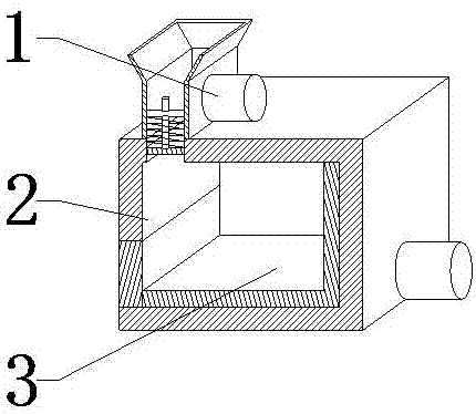
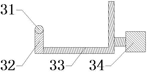
[0020] see Figure 1-Figure 3 , the present invention provides a technical solution: a dust cleaning device based on mining and quarrying, including a dust suction mechanism 1, a box body 2 and a push mechanism 3, the dust suction mechanism 1 is arranged at the upper end of the box body 2, and the inner bottom of the box body 2 The end assembly is equipped with a push mechanism 3 .

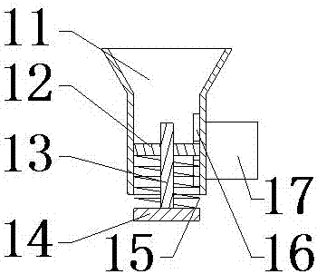
[0021] The dust suction mechanism 1 comprises a dust suction pipe 11, a fixed rod 12, a guide rod 13, a baffle plate 14, a spring 15, a rotary plectrum 16 and a dust suction fan 17. The dust suction pipe 11 is installed on the upper end of the casing 2, and the dust suction pipe 11 A fixed rod 12 is installed on the inner wall, a guide rod 13 is arranged on the fixed ro


PUM


Abstract

The invention provides a mine-based quarrying dust cleaning device which comprises a dust suction pipe, fixed rods, guide rods, baffles, springs, rotary stirring pieces, a dust suction fan, a rotary shaft, a movable door plate, an L-shaped push plate and an electric cylinder. The fixed rods are mounted on the inner wall of the dust suction pipe and provided with the guide rods, the springs are mounted on the guide rods, and the guide rods and the springs are assembled at the upper ends of the baffles. The dust suction fan is mounted at the right end of the dust suction pipe and penetrates the dust suction pipe to be connected with the rotary stirring pieces. By means of the design, dust can be automatically absorbed. The rotary shaft is arranged at the upper end of the movable door plate, the L-shaped push plate is mounted at the right end of the movable door plate, and the electric cylinder is mounted at the right end of the L-shaped push plate. By means of the design, dust can be automatically pushed. The mine-based quarrying dust cleaning device is convenient to use and operate and can achieve automatic collection, and the dust is automatically pushed.

Description


Claims


Application Information

Patent Timeline
Owner 洛阳益矿机械设备有限公司
Why Eureka
Try Eureka