Pressure cooking utensil

A technology of cooking utensils and pressure, applied in the direction of pressure cooker, etc., can solve the problems of cumbersome assembly process, low efficiency, complex structure, etc., and achieve the effect of simplifying assembly process, facilitating assembly, and avoiding assembly errors

Pending Publication Date: 2018-01-05
ZHEJIANG SUPOR ELECTRICAL APPLIANCES MFG CO LTD
View PDF11 Cites 2 Cited by
  • Summary
  • Abstract
  • Description
  • Claims
  • Application Information

AI Technical Summary

Problems solved by technology

The existing pressure valve and safety valve are two independent systems. During the assembly process of pressure cooking utensils, the pressure valve and safety valve usually need to be installed separately, and corresponding positioning needs to be done respectively. The structure is complex and the assembly process is difficult. Cumbersome, complex and inefficient

Method used


Image

  • Pressure cooking utensil
  • Pressure cooking utensil
  • Pressure cooking utensil

Examples


Example Embodiment

[0021] In the following description, a lot of specific details are given in order to provide a more thorough understanding of the present invention. However, it is obvious to those skilled in the art that the embodiments of the present invention can be implemented without one or more of these details. In other examples, in order to avoid confusion with the embodiments of the present invention, some technical features known in the art are not described.

[0022] In order to thoroughly understand the embodiments of the present invention, a detailed structure will be proposed in the following description. Obviously, the implementation of the embodiments of the present invention is not limited to the specific details familiar to those skilled in the art. The preferred embodiments of the present invention are described in detail as follows. However, in addition to these detailed descriptions, the present invention may also have other embodiments.

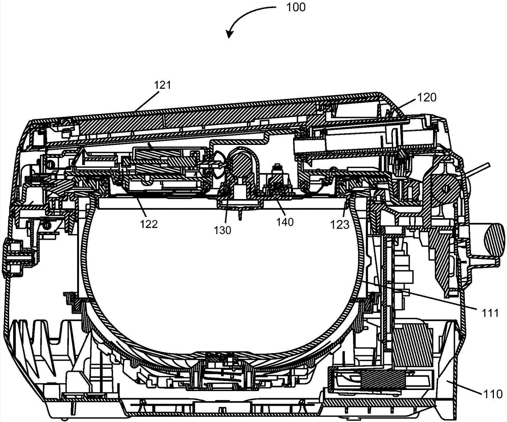
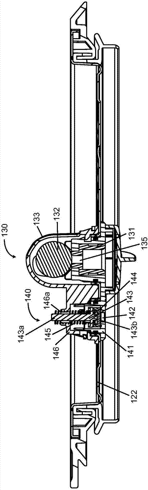
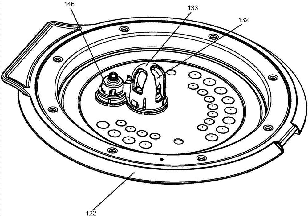
[0023] Below, refer to Figure 1-4 The


PUM


Abstract

The invention discloses a pressure cooking utensil, comprising a pot body, a cover body, a safety valve assembly, and a pressure valve assembly. The safety valve assembly is arranged in the cover body, and comprises a safety valve seat, a safety valve cover, a sealing pad, and an elastic piece. The bottom of the safety valve seat is provided with an exhaust port communicated with an inner pot. Thesafety valve cover is assembled on the safety valve seat and the top of the safety valve cover is provided with a hole. The sealing pad is arranged in the safety valve seat, and is used to seal the exhaust port. The elastic piece acts between the sealing pad and the safety valve cover. The pressure valve assembly is arranged in the cover body, and includes a pressure valve seat, a pressure valvecover assembled on the pressure valve seat, and a gravity ball arranged in the pressure valve cover. The pressure valve seat is internally provided with a steam discharge hole. The gravity ball opensand closes the steam discharge hole, to realize sealing and discharge of steam, wherein the safety valve seat and the pressure valve seat are all-in-one pieces which are formed integrally. The pressure cooking utensil provides convenience for installation of the safety valve assembly and the pressure valve assembly.

Description


Claims


Application Information

Patent Timeline
Owner ZHEJIANG SUPOR ELECTRICAL APPLIANCES MFG CO LTD
Why Eureka
Try Eureka