Novel damping suspension

A new type of suspension technology, applied in the direction of power plant, jet propulsion device, internal combustion propulsion device, etc., can solve the problems of process and simulation error, consume a lot of manpower, material resources, time, vibration, etc., to avoid resonance and solve vibration noise Problems, Effects of Simple Structure

Pending Publication Date: 2018-01-23
AUTOMOBILE RES INST OF TSINGHUA UNIV IN SUZHOU XIANGCHENG
View PDF21 Cites 2 Cited by
  • Summary
  • Abstract
  • Description
  • Claims
  • Application Information

AI Technical Summary

Benefits of technology

This innovation improves upon existing designs for reducing vibrations from vehicles without causing damage or affects their performance. It achieves this through adding an improved design called Vibrating Dampers (VMD). By controllably changing its weight, VMD allows for more flexibility when selecting which mode they are used on each car's wheelbase. Additionally, there will also help prevent these modes being excited near certain harmonics due to nearby sources like engine sounds. Overall, this technology helps improve safety standards while still maintaining good driving experience during different types of road conditions such as rainwater puddles, snow covered roads, etc., resulting in better overall quality control measures over all cars.

Problems solved by technology

The technical problem addressed in this patents relates to improving the performance of vehicles while reducing their emissions without compromising its overall quality or safety standards. One solution involves adding rubber components called springs between different parts of the structure of the suspended mass transfer system. These spring systems help absorb some energy transferred through these areas when they come into contact with certain surfaces like roads, thereby preventing them from causing damage. However, traditional methods used to achieve desired results often result in reduced vibrations at lower frequencies than what was previously hoped. Therefore, new designs aim towards achieving better vibration insulation over all possible operating ranges.

Method used


Image

  • Novel damping suspension
  • Novel damping suspension
  • Novel damping suspension

Examples


Embodiment Construction

[0021] The technical solution of the present invention will be further described below in conjunction with the accompanying drawings.

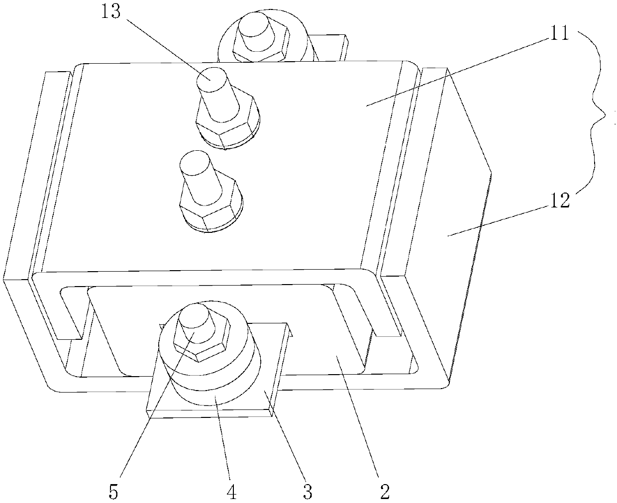
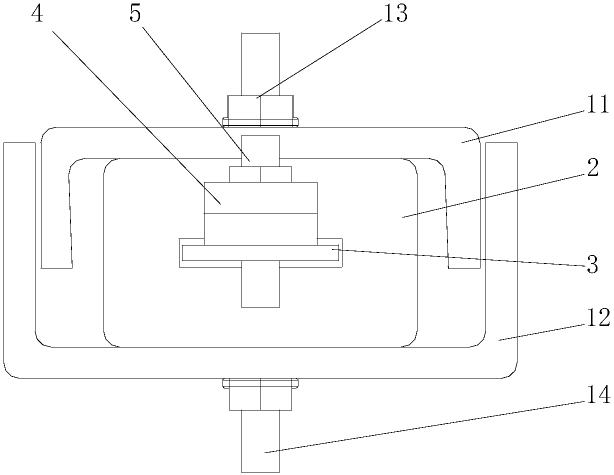
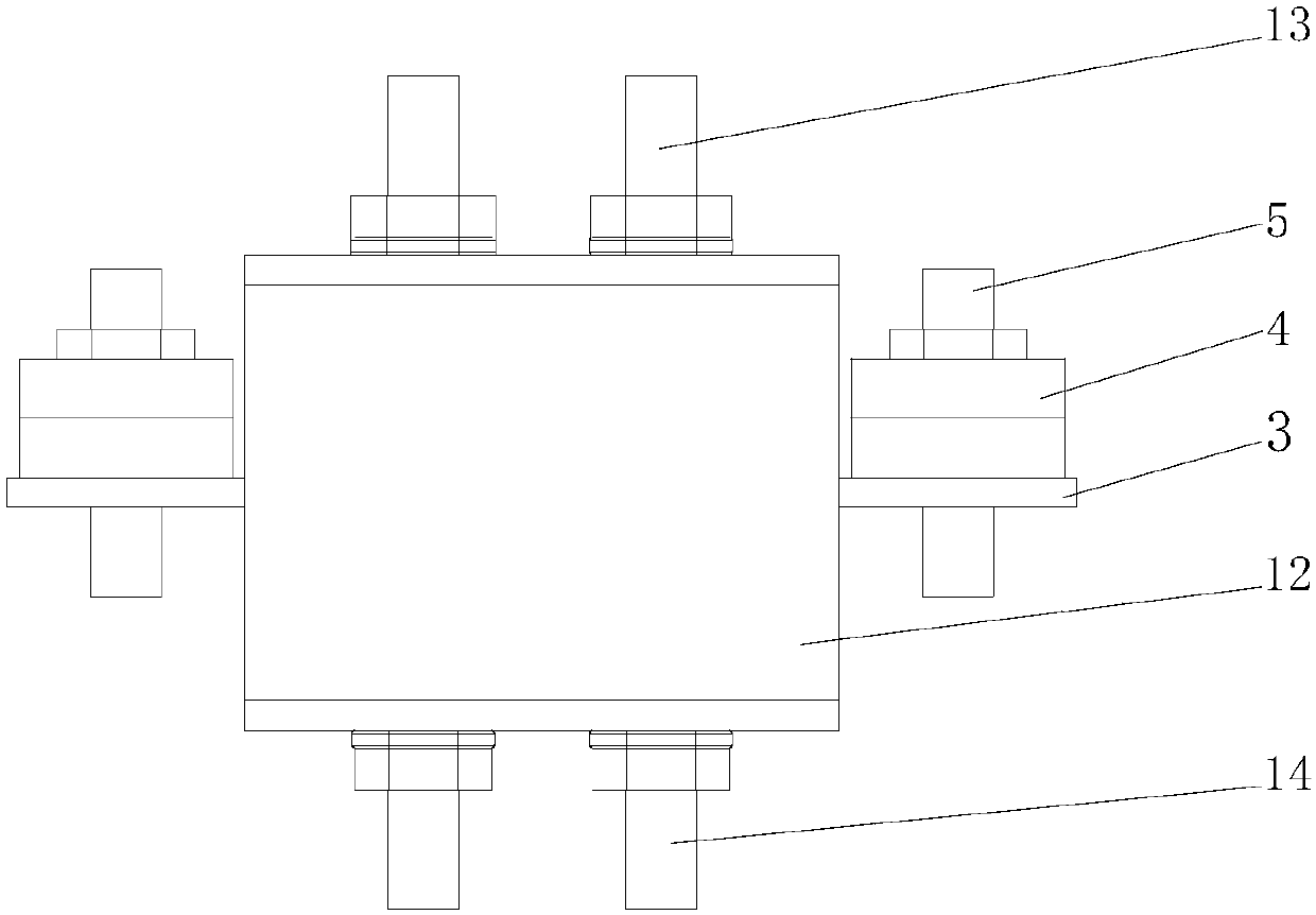
[0022] The novel damping mount of the present invention is arranged between the automobile engine and the automobile chassis, such as Figure 1~Figure 3 As shown, the vibration damping suspension includes a shell 1 , a rubber part 2 , a metal plate 3 and a mass block 4 .

[0023] The casing 1 includes an upper casing 11 and a lower casing 12, and the rubber part 2 is arranged between the upper casing 11 and the lower casing 12. In this embodiment, the upper casing 11 has a U-shaped structure with the opening facing downward, and the lower The casing 12 has a U-shaped structure with an opening facing upwards, and the two sides of the U-shaped structure of the lower casing 12 are located outside the two sides of the U-shaped structure of the upper casing 11 . On the upper housing 11, a first bolt 13 is fixed, and the first bolt 13 is used to conne


PUM


Abstract

The invention discloses a novel damping suspension. The damping suspension is respectively connected with an automobile engine and an automotive chassis. The damping suspension comprises a housing, arubber part, a metal plate and a mass block. The rubber part is fixedly arranged in the housing. The metal plate passes through the rubber part and protrudes from a side surface of the rubber part. The mass block is disposed on a portion of the metal plate protruding from the rubber part. The damping suspension is simple in structure, can adjust rigidity of the damping suspension by adjusting massof the mass block, so as to solve the vibration noise problem caused by the vibration frequency of the damping suspension higher than a target value, and can prevent the damping suspension near othermodal frequencies of a whole automobile from producing resonancesimultaneously.

Description


Claims


Application Information

Patent Timeline
Owner AUTOMOBILE RES INST OF TSINGHUA UNIV IN SUZHOU XIANGCHENG
Why Eureka
Try Eureka