Medical trolley

A trolley and push mechanism technology, applied in the field of trolleys, can solve the problems of pollution of medical equipment and medical equipment, affect the work efficiency of medical personnel, and unclear classification of storage locations, so as to avoid pollution, increase functionality and convenience, and avoid clutter effect

Inactive Publication Date: 2018-02-06
成都亿方世佳科技有限公司
View PDF0 Cites 2 Cited by
  • Summary
  • Abstract
  • Description
  • Claims
  • Application Information

AI Technical Summary

Problems solved by technology

[0002] In hospitals, medical personnel often have a lot of medical supplies, medical appliances and other items that need to be stored correctly during their work. At present, the medical trolleys commonly used in hospitals are simple and applicable, but at the same time, there are

Method used


Image

  • Medical trolley
  • Medical trolley
  • Medical trolley

Examples


Example Embodiment

[0013] The present invention will be further described below in conjunction with the description of the drawings and the embodiments. The manner of the present invention includes but is not limited to the following embodiments.

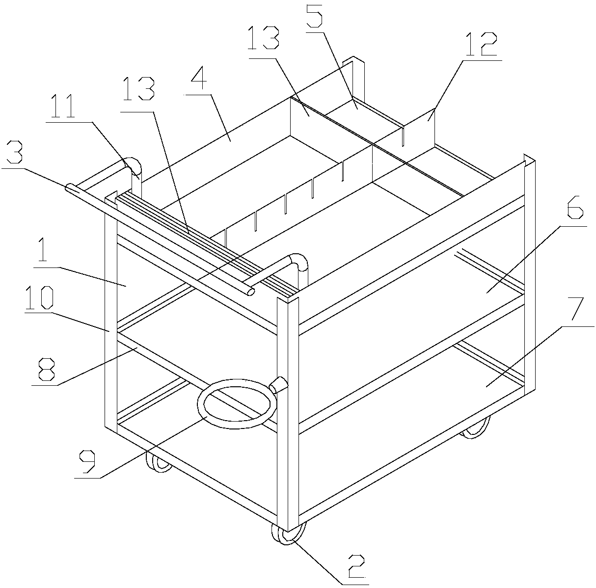
[0014] Such as figure 1 As shown, a medical trolley includes a trolley body 1, a pushing mechanism provided on the body, and a pulley 2 provided below the body. The body 1 includes an upper base plate 5, a middle base plate 6 and a lower base plate 7, and the upper base plate , The middle bottom plate and the lower bottom plate are both set on the cross bar 8, the two ends of the cross bar are respectively connected with the uprights 10, one of the uprights is also provided with a storage ring 9; the pushing mechanism is set on the upper bottom plate One side of 5 includes two support rods 11 directly arranged on the upper bottom plate, and push rods 3 whose two ends are respectively connected to the upper ends of the two support rods; the upper bottom plate


PUM


Abstract

The invention discloses a medical trolley, comprising a trolley body, a pushing mechanism and a pulley. The body includes an upper bottom plate, a middle bottom plate and a lower bottom plate, and the upper bottom plate, the middle bottom plate and the lower bottom plate are all arranged on a cross bar. The two ends of the crossbar are respectively connected with the uprights, and a storage ring is also arranged on one of the uprights; the pushing mechanism is arranged on one side of the upper bottom plate, including two struts directly arranged on the upper bottom plate, and a push rod whose two ends are respectively connected with the upper ends of the two support rods; a baffle plate is arranged on the upper base plate and surrounds the three-side edges of the pushing mechanism, and a separation mechanism for partitioning the upper base plate is arranged on the upper base plate; the separation The mechanism includes vertical baffles and horizontal baffles. The trolley can realize the classification and placement of large medical tools and small medical tools without enlarging the volume of the body, and can also be used to prevent medical tools from being discarded, and has strong functionality and convenience.

Description


Claims


Application Information

Patent Timeline
Owner 成都亿方世佳科技有限公司
Why Eureka
Try Eureka