Positioning finder

A finder and resonant chamber technology, applied in the field of positioning equipment, can solve the problems of inconvenient use and power consumption of speakers, and achieve the effects of light and thin overall structure, low power consumption and convenient installation

Pending Publication Date: 2021-11-23
泉州新汉特箱包轻工有限公司
View PDF0 Cites 0 Cited by
  • Summary
  • Abstract
  • Description
  • Claims
  • Application Information

AI Technical Summary

Problems solved by technology

Existing vocal positioning finders mainly use loudspeakers to prompt and alarm. The loudspeakers consume a lot of power during use, and the general service life is only 3-5 days. After the power is exhausted, the battery needs to be replaced, which is extremely inconvenient to use.

Method used


Image

  • Positioning finder
  • Positioning finder
  • Positioning finder

Examples


Example Embodiment

[0036] Example 1:

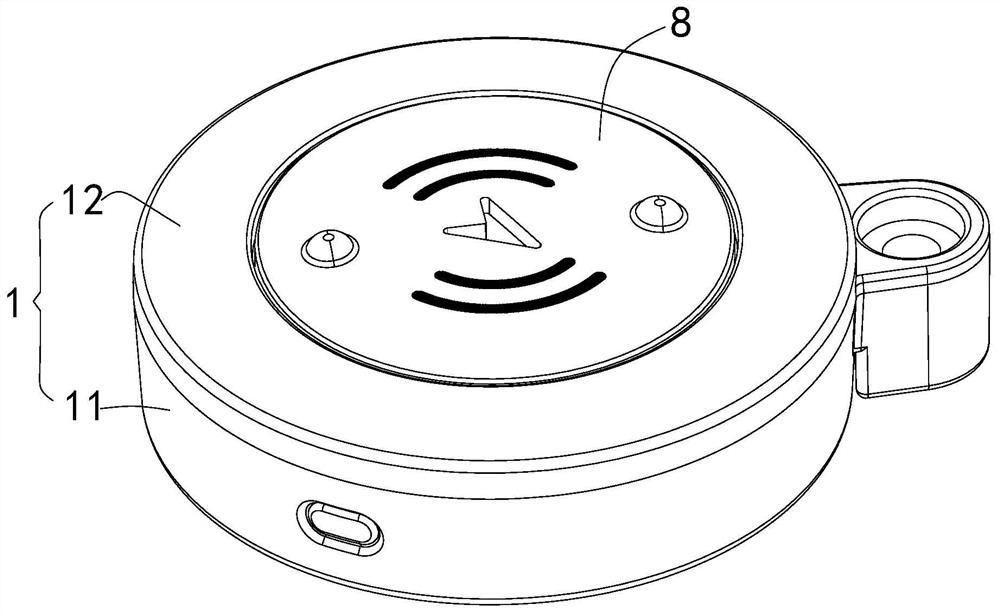
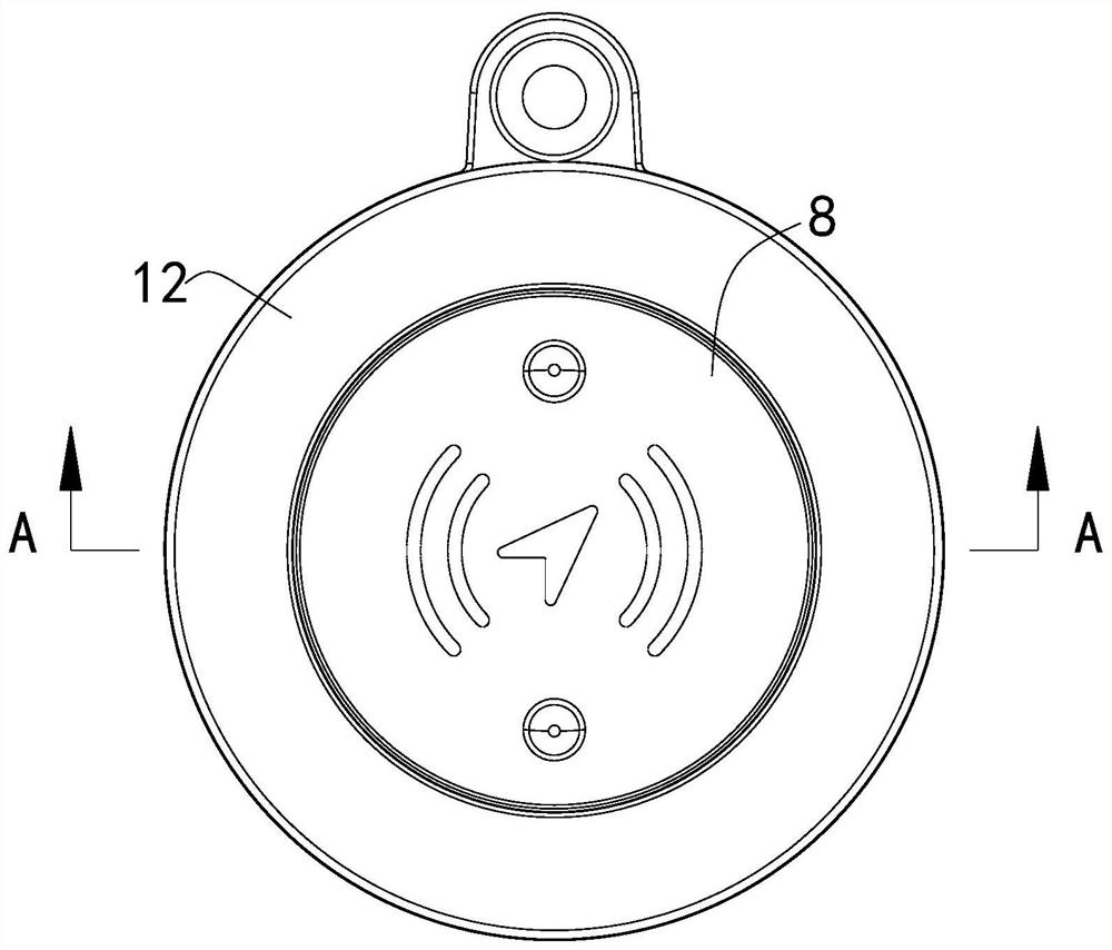
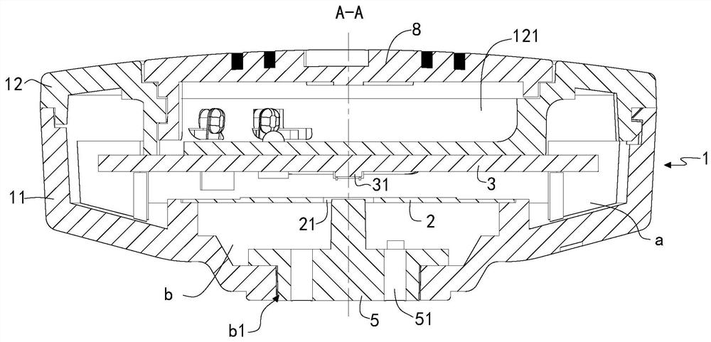
[0037] like Figure 1-8 As shown, a positioning finder comprising a housing 1, and an inner portion of the housing 1 is provided at the first total rumor A, located below the second residential cavity B and for the first The resonance chamber A and the second covarian B are separated and used in the buzzer 2, the positioning finder further includes a main board 3 for controlling the buzzer 2 in which the buzzer 2 is connected. And a power supply device for powering with the motherboard 3 is connected to the motherboard 3.

[0038] The positioning finder uses the buzzer 2 to vote, compared to the sound elements such as the buzzer or speaker, the buzzer 2 has a small power consumption, longer use, and the use of the button battery can be met. The buzzer 2 is mainly composed of a piezoelectric ceramic plate and a metal plate brass or stainless steel. When the adhesive is used, the piezoelectric vibrating plate and the metal sheet are bonded together, and when the DC v

Example Embodiment

[0055] Example 2:

[0056] like Figure 9 As shown, the difference from the embodiment is connected between the main board 3 and the buzzer 2 through the elastic folded pin 7. The connection between the main board 3 and the buzzer 2 is performed using the elastic folded foot 7, and the overall structure of the positioning lookup can be thinner than the connection of the thimble 6.


PUM

PropertyMeasurementUnit
Outer diameteraaaaaaaaaa
Thicknessaaaaaaaaaa
Diameteraaaaaaaaaa

Abstract

The invention relates to the field of positioning equipment, in particular to a positioning finder which comprises a shell (1), a first resonance cavity (a) located on the upper portion, a second resonance cavity (b) located on the lower portion and a buzzing piece (2) used for sounding are arranged in the shell (1), and the buzzing piece (2) separates the first resonance cavity (a) from the second resonance cavity (b). The positioning finder further comprises a mainboard (3) which is connected with the buzzing piece (2) and is used for controlling the buzzing piece (2) to be powered on and powered off, and a power supply device which is connected with the mainboard (3) and is used for supplying power to the mainboard (3). According to the positioning finder, the defects of the existing positioning finder can be overcome, and the effects of power saving and large sound production volume of the positioning finder are achieved.

Description


Claims


Application Information

Patent Timeline
Owner 泉州新汉特箱包轻工有限公司
Why Eureka
Try Eureka