Disaster recovery switching method, node and system

A disaster recovery switching and node technology, which is applied in transmission systems, digital transmission systems, data exchange networks, etc., can solve the problems of data loss in disaster recovery switching, and achieve the goal of improving data disaster tolerance, ensuring consistency, and ensuring stability Effect

Inactive Publication Date: 2018-02-13
HUAWEI TECH CO LTD
View PDF11 Cites 12 Cited by
  • Summary
  • Abstract
  • Description
  • Claims
  • Application Information

AI Technical Summary

Problems solved by technology

[0006] The present invention provides a method, node and system for disaster recovery switching,

Method used


Image

  • Disaster recovery switching method, node and system
  • Disaster recovery switching method, node and system
  • Disaster recovery switching method, node and system

Examples


Embodiment Construction

[0105] The technical solutions in the embodiments of the present invention will be clearly and completely described below in conjunction with the accompanying drawings in the embodiments of the present invention. Obviously, the described embodiments are only some of the embodiments of the present invention, not all of them. Based on The embodiments of the present invention, and all other embodiments obtained by those skilled in the art without creative efforts, all belong to the protection scope of the present invention.

[0106] The terms "first", "second" and the like in the description and claims of the present invention and the above drawings are used to distinguish similar objects, and are not necessarily used to describe a specific sequence or sequence. It is to be understood that the terms so used are interchangeable under appropriate circumstances such that the embodiments described herein can be practiced in sequences other than those illustrated or described herein. Fur


PUM


Abstract

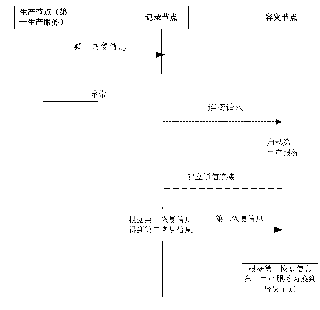
A disaster recovery switching method, a node and a system are provided. The method is applied to a disaster recovery switching system. The disaster recovery switching system includes a production node, a disaster recovery node and a recording node. The production node currently runs a first production service. The method includes the steps that the recording node receives first recovery information sent by the production node, wherein the first recovery information refers to the information required for recovering the first production service to a latest running state of the first production service; and the recording node sends second recovery information to the disaster recovery node when it is determined that the first production service is recovered on the disaster recovery node, wherein the second recovery information refers to the information required for recovering the first production service on the disaster recovery node obtained according to the first recovery information tomake the disaster recovery node switch the first production service to the disaster recovery node according to the second recovery information. The disaster recovery switching method, the node and thesystem can achieve the seamlessly switching of business, ensure the normal operation of the business, improve the stability of the production service and effectively avoid data loss in the event of asudden disaster on the production node.

Description


Claims


Application Information

Patent Timeline
Owner HUAWEI TECH CO LTD
Why Eureka
Try Eureka