High-pressure rotary joint

A rotary joint, high-pressure technology, applied in the direction of pipes/pipe joints/fittings, adjustable connections, passing components, etc., can solve problems such as oil leakage, rotary joints cannot be effectively sealed, and affect work, etc., to achieve good sealing effect and simple structure , Stable and reliable performance

Inactive Publication Date: 2018-02-16
CHANGZHOU CHANGTONG PLASTIC PIPE
View PDF0 Cites 3 Cited by
  • Summary
  • Abstract
  • Description
  • Claims
  • Application Information

AI Technical Summary

Benefits of technology

This innovation makes it easier for people who want better protection from harm or damage caused by firearms without adding extra weight on their hands. It's also easy-to-use with different types of weapons that can be used against them safely.

Problems solved by technology

This patents describes how wind-power plants use high pressures on an oily liquid called water during operation due to its unique characteristics such as being able to withstand very strong forces without leaks or losing effectiveness over time. However, current methods often require multiple rotational joints at different locations within the machine, which makes them difficult to maintain securely when working properly below 15 MPa.

Method used


Image

  • High-pressure rotary joint

Examples


specific Embodiment approach

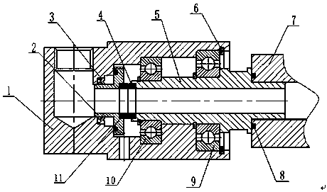
[0012] Examples, see attached figure 1 , a high-pressure rotary joint, characterized in that it includes a housing 1, a mounting seat 2, a left sealing ring 3, a moving ring 4, a rotating shaft 5, a retaining ring 6 for a hole, a bracket 7, a right sealing ring 8, a right rolling bearing 9, The left rolling bearing 10 and the static ring 11, the right end of the housing 1 in the horizontal direction is processed with a stepped hole, the vertical direction is processed with a cylindrical hole and the two holes are connected, the left end surface of the mounting seat 2 is processed with a groove, the mounting seat 2 is fixedly installed on the end face of the inner hole at the right end of the casing 1, the left sealing ring 3 is installed at the left end of the mounting seat 2, the moving ring 4 is fixedly installed in the groove at the left end of the rotating shaft 5 and closely fits with the static ring 11, so The outer ring of the left rolling bearing 10 is installed in the in


PUM


Abstract

The invention discloses a high-voltage rotary joint. The main contents are as follows: a stepped hole is machined at the right end of the casing in the horizontal direction; Installed on the left end of the mounting seat, the moving ring is fixedly installed in the groove on the left end of the rotating shaft and closely fits with the static ring, the outer ring of the left rolling bearing is installed in the inner hole of the casing, the inner ring of the left rolling bearing is sleeved on the rotating shaft, and its right end is on the rotating shaft. On the step on the left end of the shaft, the outer ring of the right rolling bearing is installed in the inner hole of the casing, and its right end is abutted on the left end face of the retaining ring for the hole installed in the groove at the right end of the casing, and the left end of the inner ring of the right rolling bearing is installed on the rotating shaft through The hole is fixed with a retaining ring, the right end of which is on the step on the rotating shaft, the central position of the rotating shaft is machined with an inner hole along the axis direction, the right end of the rotating shaft is installed in the threaded hole of the bracket through a threaded connection, and a joint is installed between the two joint surfaces. Right seal.

Description


Claims


Application Information

Patent Timeline
Owner CHANGZHOU CHANGTONG PLASTIC PIPE
Why Eureka
Try Eureka