Height difference retention method of hoisting cushion blocks of exterior wall cladding
A pad and height technology, which is applied in the field of installation and adjustment of building components, can solve problems affecting the stability and firmness of components, manufacturing errors, etc., and achieve the effect of fast and accurate installation and preventing shaking
- Summary
- Abstract
- Description
- Claims
- Application Information
AI Technical Summary
Benefits of technology
Problems solved by technology
Method used
Image

Examples
Embodiment 1
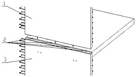
[0032] refer to Figure 1~2 :
[0033] In this embodiment, a method for height difference of the prefabricated component hoisting pad 2 includes the upper component 1, the lower component 3 and the pad 2, and the specific steps are as follows:
[0034] 1) The upper member 1 is pre-hoisted, and the upper member 1 is hoisted above the lower member 3 and then stopped;
[0035] 2) Placement and adjustment of pads 2, place several pads 2 on the lower member 3, the height of the pads 2 in the middle is lower than the pads 2 at both ends;
[0036] 3) The upper member 1 is hoisted in place, and the upper member 1 is dropped and placed on the block 2;
[0037] 4) Adjust the position of the upper member 1, and adjust the placement position of the upper member 1 to coincide with the preset position.
[0038] In the present invention, the upper component 1 is a prefabricated component such as a prefabricated wall, a prefabricated beam or a prefabricated floor. After the upper component 1
Embodiment 2
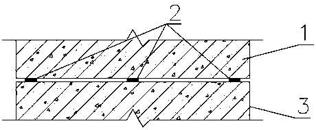
[0047] refer to image 3 :
[0048] Compared with Embodiment 1, there are the following differences in the height difference method of a prefabricated component hoisting pad 2 in this embodiment:
[0049] A positioning piece is provided outside the positioning line at the preset position, and the positioning piece includes a bottom plate and a vertical plate arranged on one side of the bottom plate. When the positioning piece is placed, the vertical plate is flush with the positioning line at the preset position, and the bottom plate is located outside of the set position.
[0050] It should be pointed out that the positioning member can be made of steel such as angle steel, square steel, etc., or can be made of steel plate or plate of other materials by welding, bonding or integral molding.
[0051] In this embodiment, by placing the positioning device next to the preset position, the stability of the upper member 1 after being in place can be ensured, and it can be ensured th
Embodiment 3
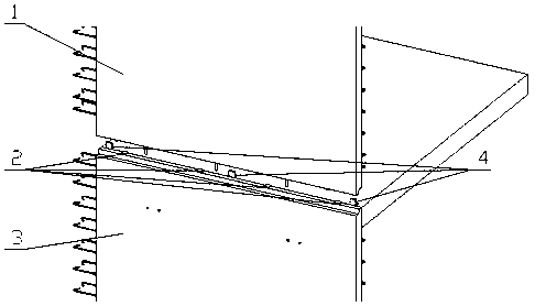
[0053] refer to Figure 4 :
[0054] Compared with Embodiment 1 or 2, there are the following differences in the height difference method of a prefabricated component hoisting pad 2 in this embodiment:
[0055] The upper end of the upper member 1 and the upper end of the lower member 3 are provided with corresponding folding grooves 5 . The positioning of the upper member 1 and the lower member 3 can be made more accurate through the folded rebate 5, and the sealing performance of the connecting surface between the two can be improved.
[0056] The spacer 2 is arranged on the upper end of the folded groove 5 , and the lower end of the folded groove 5 is provided with a drainage piece 6 . Setting the upper end of the folded groove 5 on the cushion block 2 can ensure a good supporting effect on the upper member 1, and setting the drainage member 6 at the lower end of the folded groove 5 can drain the accumulated water in the floor.
PUM
| Property | Measurement | Unit |
|---|---|---|
| Thickness | aaaaa | aaaaa |
Abstract
Description
Claims
Application Information
 - R&D Engineer
- R&D Manager
- IP Professional
- Industry Leading Data Capabilities
- Powerful AI technology
- Patent DNA Extraction
Browse by: Latest US Patents, China's latest patents, Technical Efficacy Thesaurus, Application Domain, Technology Topic.
© 2024 PatSnap. All rights reserved.Legal|Privacy policy|Modern Slavery Act Transparency Statement|Sitemap