Cylinder swinging type slag falling device adopted during waste pyrolysis

A swinging, pyrolysis technology, applied in the direction of lighting and heating equipment, combustion methods, combustion types, etc., can solve the problems of cumbersome operation, laborious, dust flying and unhygienic, and achieve the improvement of automation, sanitation conditions and labor intensity. Reduced effect

Active Publication Date: 2018-02-23
湖南奔骥环保能源科技有限责任公司
View PDF6 Cites 0 Cited by
  • Summary
  • Abstract
  • Description
  • Claims
  • Application Information

AI Technical Summary

Problems solved by technology

[0002] Domestic waste treatment equipment, especially the furnace grate slag extraction of oxygen-controlled pyrolysis equipme

Method used


Image

  • Cylinder swinging type slag falling device adopted during waste pyrolysis
  • Cylinder swinging type slag falling device adopted during waste pyrolysis

Examples


Embodiment Construction

[0016] The present invention is further described in conjunction with the following examples.

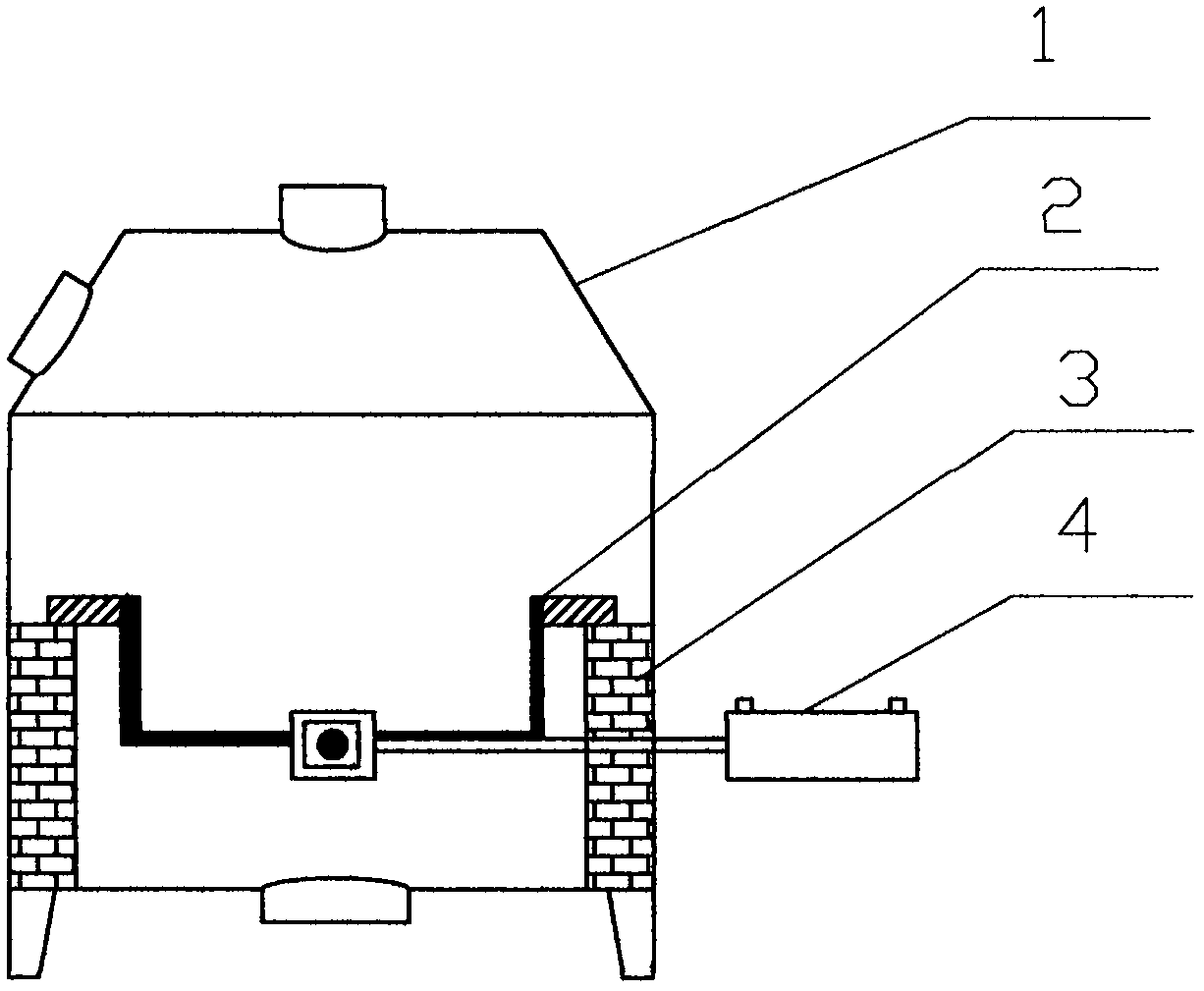
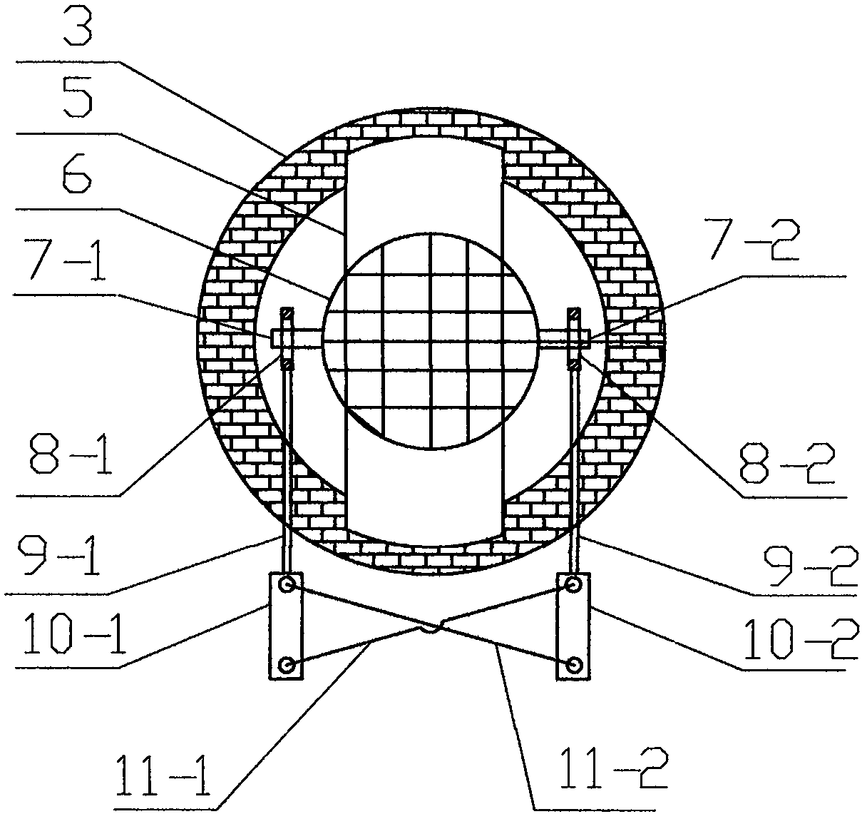
[0017] A cylinder swing type slag removal device is used in the pyrolysis of garbage in this embodiment. The present invention consists of a pyrolysis upper furnace body (1), a grid-type pyrolysis frame (2), a pyrolysis lower furnace body (3), and a cylinder swing The slag remover (4) consists of: the pyrolysis upper furnace body (1) is connected with the pyrolysis lower furnace body (3); on the step of the pyrolysis lower furnace body (3), a grid-shaped pyrolysis frame (2 ); on both sides of the grid-type pyrolysis frame (2), a cylinder swinging slag remover (4) is arranged, and the both sides of the grid-type pyrolysis frame (2) are provided with support ear one (7-1) and support Ear two (7-2) is matched with cylinder swing slag remover (4).

[0018] A cylinder swing type slag removal device is used for the pyrolysis of garbage, and the grid-shaped pyrolysis frame (2) consists of lu


PUM


Abstract

The invention discloses a cylinder swinging type slag falling device adopted during waste pyrolysis. The cylinder swinging type slag falling device adopted during waste pyrolysis is composed of a pyrolysis upper furnace body (1), a grid type pyrolysis frame (2), a pyrolysis lower furnace body (3) and a cylinder swinging slag falling unit (4), wherein the pyrolysis upper furnace body (1) is connected with the pyrolysis lower furnace body (3); the grid type pyrolysis frame (2) is placed on the step of the pyrolysis lower furnace body (3); the cylinder swinging slag falling unit (4) is arranged on the two sides of the grid type pyrolysis frame (2); and a first supporting lug (7-1) and a second supporting lug (7-2) are arranged on the two sides of the grid type pyrolysis frame (2) to be matched with the cylinder swinging slag falling unit (4). The cylinder swinging type slag falling device adopted during waste pyrolysis is novel in structure, by arranging the cylinder swinging slag fallingunit, the supporting lugs can be pushed during cylinder swinging, then the grid type pyrolysis frame can be pushed, domestic garbage slag materials in the grid type pyrolysis frame after pyrolysis can automatically fall in a shaking manner, the troublesome that the slag materials need to be manually pulled out little by little is avoided, and very high practicability is achieved.

Description


Claims


Application Information

Patent Timeline
Owner 湖南奔骥环保能源科技有限责任公司
Why Eureka
Try Eureka