Oilfield well testing vehicle electric drive system

A technology of well testing and vehicle electricity, which is applied in general control systems, control/regulation systems, wellbore/well components, etc., can solve problems such as low control accuracy, high labor intensity of workers, and inability to meet the requirements of modern oilfield production. Low useless energy consumption and high energy conversion effect

Pending Publication Date: 2018-03-02
WEIHAI HHH MACHANICAL & ELECTRICAL
View PDF1 Cites 0 Cited by
  • Summary
  • Abstract
  • Description
  • Claims
  • Application Information

AI Technical Summary

Problems solved by technology

Chinese Patent Publication (Announcement) No. CN2193426, published on March 29, 1995, discloses a hydraulic well testing vehicle, which consists of a special vehicle modified by adding a closed compartment to the chassis of a truck and a well logging device. The winch of the device is driven by the output power of the vehicle transmission, which is characterized in that the transmission system of the winch is a hydraulic transmission system, that is, a power take-off is installed on the side of the automobile gearbox, and the power is directly drawn from the gearbox; Drive the hydraulic pump of the hydraulic transmission system through the coupling mechanism; then the hydraulic motor drives the winch through the coupling mechanism; the hydraulic transmission system adopts the integrated block hydraulic distributor. strong
With the rapid development of oil production in oil fields, this control system can no longer meet the needs of modern production in oil fields

Method used


Image

  • Oilfield well testing vehicle electric drive system

Examples


Example Embodiment

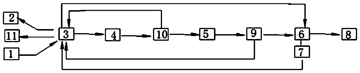
[0016] The present invention will be further explained below in conjunction with the drawings:

[0017] As shown in the figure, an oil field test vehicle electric drive system includes a console. The console is equipped with a control component 1 and a liquid crystal display 2. It is characterized by a PLC controller 3, a generator 4, a rectifier unit 5. The vector inverter 6, the winch motor 8, the vector inverter 6 is equipped with a Hall torque sensor 7, the power output terminal of the generator 4 is connected to the input terminal of the rectifier unit 5, and the output terminal of the rectifier unit 5 is rectified and its output terminal is input to the vector inverter 6 The input terminal of the vector inverter 6 is connected with the winch motor 8 to drive the winch motor. There is an undervoltage protector 9 between the rectifier unit 5 and the vector inverter 7, and between the generator 4 and the rectifier unit 5. The leakage protector 10 and the electric drive system are


PUM


Abstract

The invention relates to the technical field of oil and gas well detection, in particular to an electric drive system of an oil field well test vehicle, which includes a console on which a control component and a liquid crystal display are arranged, and the electric drive system includes a control component, a liquid crystal display, a Hall torque Sensors, PLC controllers, generators, rectifier units, vector inverters and winch motors, in which the control components and Hall torque sensors are connected to the PLC controller through input circuits, and the PLC controllers are respectively connected to the vector inverter through output circuits. The input terminal and the generator input terminal are connected to the LCD display, the power output terminal of the generator is connected to the input terminal of the rectifier unit, the output terminal of the rectifier unit is connected to the input terminal of the vector inverter after rectification, and the output terminal of the vector inverter is connected to the winch motor. To drive the winch motor, due to the above structure, the present invention has the advantages of small size, high power, low cost, convenient installation and easy maintenance.

Description


Claims


Application Information

Patent Timeline
Owner WEIHAI HHH MACHANICAL & ELECTRICAL
Why Eureka
Try Eureka