Pull rod linkage mechanism

A linkage mechanism and tie rod technology, applied in mechanical equipment, transmission, belt/chain/gear, etc., can solve the problem of increased error of auxiliary parts, and achieve the effect of improving service life and simple overall structure.

Inactive Publication Date: 2018-03-06
范琴
View PDF0 Cites 2 Cited by
  • Summary
  • Abstract
  • Description
  • Claims
  • Application Information

AI Technical Summary

Problems solved by technology

[0002] In engineering applications, some active rods and driven rods that cannot be directly connected need to rely on the linkage mechanism of the pull rod to realize the transmission of motion, and the combinati

Method used


Image

  • Pull rod linkage mechanism
  • Pull rod linkage mechanism

Examples


Embodiment Construction

[0017] The technical scheme of the present invention will be described in further detail below in conjunction with the accompanying drawings and specific embodiments, so that those skilled in the art can better understand the present invention and implement it, but the examples given are not intended to limit the present invention.

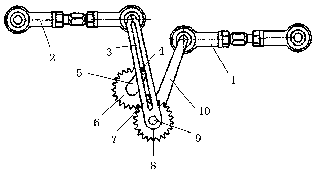
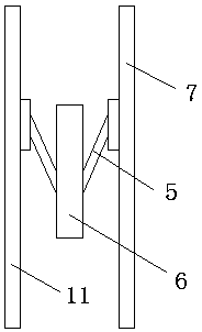
[0018] Such as figure 1 and 2 As shown, a pull rod linkage mechanism includes an active rod 1 and a driven rod 2, the active rod 1 is connected with the first gear 8 through the connecting rod 10, and the first gear 8 is hinged on the frame, namely figure 1 The position of the middle hinge point 9, the first gear 8 is meshed with the second gear 6, the first rocker 7 is arranged between one side of the driven lever 2 and one side of the first gear 8 and the driven A second rocker 11 is arranged between the other side of the rod 2 and the other side of the first gear 8 .

[0019] The first rocker 7 and the second rocker 11 are arranged parallel to e


PUM


Abstract

The invention discloses a pull rod linkage mechanism, which comprises a driving rod and a driven rod, the driving rod is connected with a first gear through a connecting rod, the first gear is hinged on a frame, and the first The gears are meshed, a first rocker is arranged between one side of the driven lever and one side of the first gear, and a second rocker is arranged between the other side of the driven lever and the other side of the first gear. The first rocker and the second rocker are arranged parallel to each other and slide grooves are arranged in parallel on the first rocker and the second rocker, and rocker arms are respectively arranged on both sides of the second gear, and each rocker The ends of the arms are respectively provided with rollers that can slide along the sliding grooves. Improve the existing tie rod linkage mechanism to avoid the phenomenon that the long-term linkage will cause the wear of the auxiliary parts and the error of the driven movement will gradually increase, and improve the service life of the equipment and the precision of the linkage.

Description


Claims


Application Information

Patent Timeline
Owner 范琴
Why Eureka
Try Eureka