Cat scratching plate

A board and box technology, applied in the field of cat scratching boards with multiple replacement parts, can solve the problems of waste of cat scratching boards, not being environmentally friendly, and increasing the production cost of cat scratching boards

Inactive Publication Date: 2018-03-13
GINYOUNG IND CO LTD
View PDF10 Cites 1 Cited by
  • Summary
  • Abstract
  • Description
  • Claims
  • Application Information

AI Technical Summary

Problems solved by technology

[0004] 1. The wavy corrugated paper 21 needs to be bonded to each other by an adhesive layer (not shown), so it takes a lot of work time to apply the adhesive layer to the surface of the corrugated paper 21, and the adhesive layer will also increase cat scratches Fabrication cost of plate structure 2
In addition, the adhesive layer will also make the manufacturing process of the cat scratching board structure 2 not environmentally friendly
[0005] 2. When a part of the rou

Method used


Image

  • Cat scratching plate
  • Cat scratching plate
  • Cat scratching plate

Examples


Embodiment Construction

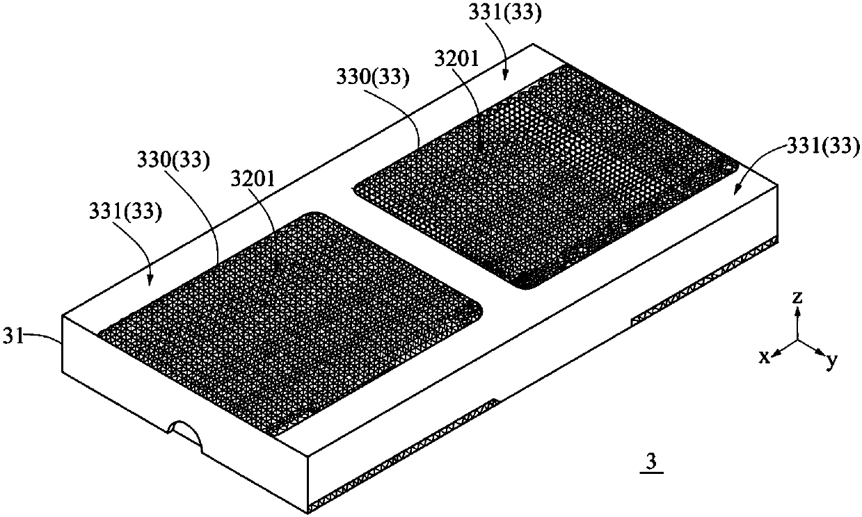
[0025] see image 3 and Figure 4 , image 3 Shown is the cat scratch board 3 of the present embodiment, Figure 4 What is shown is a schematic diagram of a plurality of replacement parts being stored inside the storage box. The cat scratching board 3 includes a storage box 31 and a plurality of replacement parts 32 , the upper surface of the storage box 31 is defined as a first surface 33 , and the first surface 33 includes two first through areas 330 . Wherein, the first penetrating region 330 completely penetrates the first surface 33 , and the remaining part of the first surface excluding the first penetrating region 330 is a cladding region 331 . In detail, the holder of the storage box 3 can directly see the inside of the storage box 3 from the first penetrating area 330, and the covering area 331 has the purpose of covering and shielding the objects inside the storage box 31 . In addition, the replacement parts 32 are closely arranged in a straight line and arranged i


PUM


Abstract

The invention provides a cat scratching plate. The cat scratching plate includes a storage box and a plurality of swapping portions; a first surface of the storage box includes at least one first throughout region; the swapping portions are arranged in a line and filled in the inner space of the whole storage box; and each swapping portion includes a first rough surface. When the swapping portionsare filled in the inner space of the whole storage box, the first rough surfaces are combined into a first rough combined surface having a large area, and the first rough combined surface is exposedin an external environment by passing through the throughout region. The beneficial effects of the invention are that the production cost of the cat scratching plate can be reduced, and damaged regions of the cat scratching plate can be rapidly changed.

Description


Claims


Application Information

Patent Timeline
Owner GINYOUNG IND CO LTD
Why Eureka
Try Eureka